11-305U Ch= 303
Crosley Radio Corp.; Cincinnati (OH)
- Country
- United States of America (USA)
- Manufacturer / Brand
- Crosley Radio Corp.; Cincinnati (OH)
- Year
- 1951 ?
- Category
- Broadcast Receiver - or past WW2 Tuner
- Radiomuseum.org ID
- 36180


Copy gen. von Bob Warren Radio Attic


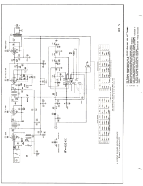
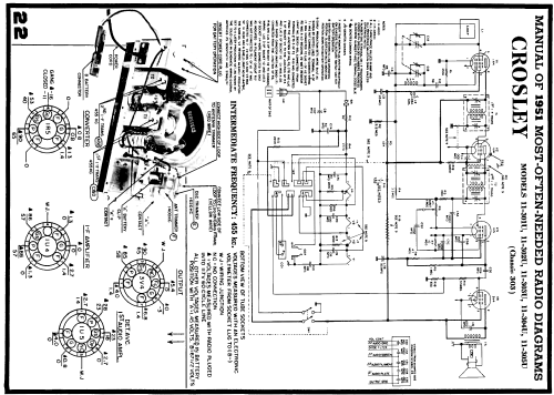
Click on the schematic thumbnail to request the schematic as a free document.
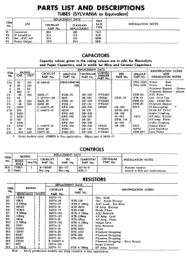
- Number of Tubes
- 4
- Main principle
- Superheterodyne (common); ZF/IF 455 kHz; 2 AF stage(s)
- Tuned circuits
- 6 AM circuit(s)
- Wave bands
- Broadcast only (MW).
- Power type and voltage
- Line / Batteries (any type) / 117V = 110 -120 / 67.5 & 1.5 Volt
- Loudspeaker
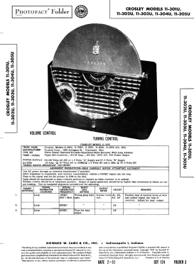
- Permanent Magnet Dynamic (PDyn) Loudspeaker (moving coil) / Ø 4 inch = 10.2 cm
- Power out
- 0.2 W (unknown quality)
- Material
- Bakelite case
- from Radiomuseum.org
- Model: 11-305U Ch= 303 - Crosley Radio Corp.;
- Shape
- Portable set > 8 inch (also usable without mains)
- Notes
-
Crosley model 11-304U is a three power operated portable superheterodyne receiver with loop antenna, Selenium Rectifier. Color Cabinet:Ebony, Color Lid: Ebony.
- External source of data
- Ernst Erb
- Source of data
- Collector's Guide to Antique Radios 4. Edition
- Circuit diagram reference
- Rider's Perpetual, Volume 21, Copyright 1950
- Mentioned in
- Beitman Radio Diagrams, Vol. 11, 1951
- Literature/Schematics (1)
- Photofact Folder, Howard W. SAMS (Date 2-51, Set 124, Folder 3)
- Literature/Schematics (2)
- Table Top Radios Vol. 1 Stein 98 (page 52)
- Other Models
-
Here you find 1812 models, 1050 with images and 1306 with schematics for wireless sets etc. In French: TSF for Télégraphie sans fil.
All listed radios etc. from Crosley Radio Corp.; Cincinnati (OH)
Collections
The model 11-305U is part of the collections of the following members.
Forum contributions about this model: Crosley Radio Corp.;: 11-305U Ch= 303
Threads: 1 | Posts: 2
Hi All,
Let me begin by stating that I am very new to radio restoration and really enjoying the experience.
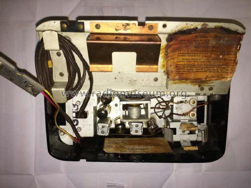
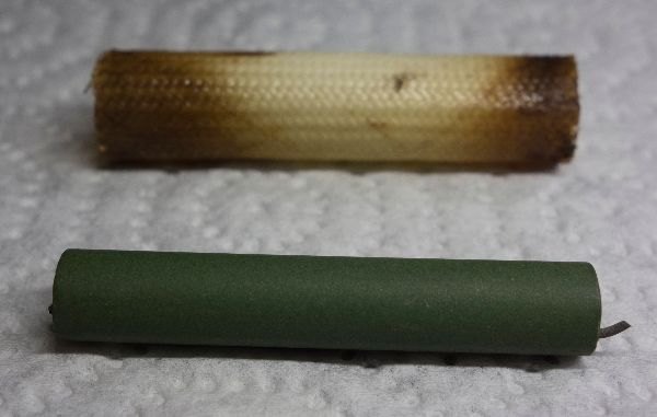
Currently working on recapping a Crosley 11-305U and discovered an unmarked capacitor under what seems to be a fire retardent cover.....See photo below. The schematic shows a rating of 2000 (with no voltage rating) for this cap and it is connected to the Output Plate. Could you please lead me to the proper replacement for this cap.....thanks for your help.
Charles Sampayo, 07.Jan.18