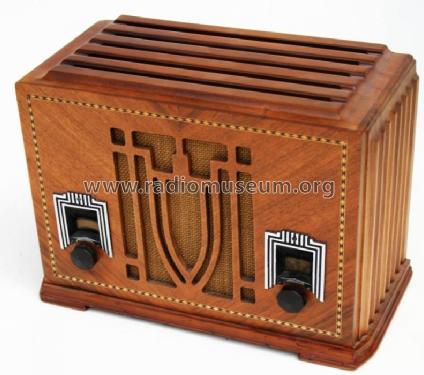
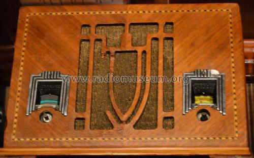
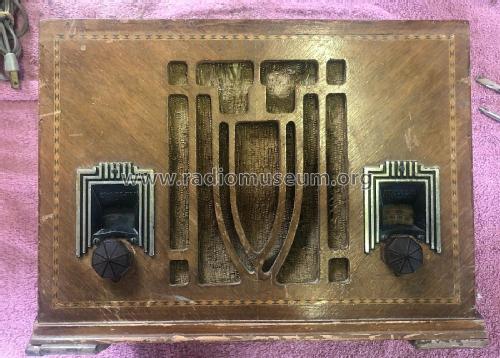
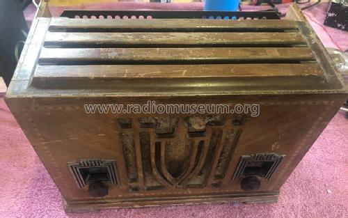
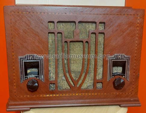
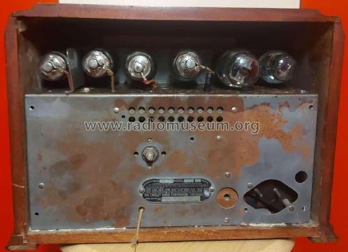
Dual Six Ch= 173
Crosley Radio Corp.; Cincinnati (OH)
- Country
- United States of America (USA)
- Manufacturer / Brand
- Crosley Radio Corp.; Cincinnati (OH)
- Year
- 1933
- Category
- Broadcast Receiver - or past WW2 Tuner
- Radiomuseum.org ID
- 36273
Click on the schematic thumbnail to request the schematic as a free document.
- Number of Tubes
- 6
- Main principle
- Superhet with RF-stage; ZF/IF 456 kHz; 1 AF stage(s)
- Wave bands
- Broadcast and Short Wave (SW).
- Power type and voltage
- AC/DC-set / 110 Volt
- Loudspeaker
- Electro Magnetic Dynamic LS (moving-coil with field excitation coil)
- from Radiomuseum.org
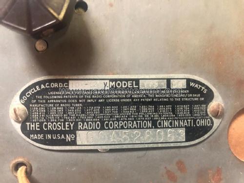
- Model: Dual Six Ch= 173 - Crosley Radio Corp.;
- Notes
- Difference to model 173-5: AC only 60 Hz. To use with model 38 power pack and remote speaker 390-6.
- External source of data
- Ernst Erb
- Circuit diagram reference
- Rider's Perpetual, Volume 4 = ca. 1934 and before
- Mentioned in
- - - Manufacturers Literature (Crosley Service Supplement Index, Suppl. 65)
- Other Models
-
Here you find 1807 models, 1050 with images and 1301 with schematics for wireless sets etc. In French: TSF for Télégraphie sans fil.
All listed radios etc. from Crosley Radio Corp.; Cincinnati (OH)
Collections
The model Dual Six is part of the collections of the following members.
Forum contributions about this model: Crosley Radio Corp.;: Dual Six Ch= 173
Threads: 1 | Posts: 1
This article may be of interest to newcomers to the hobby or interest in old radios.
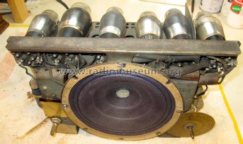
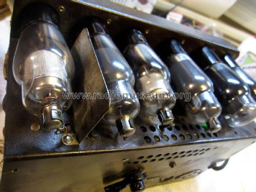
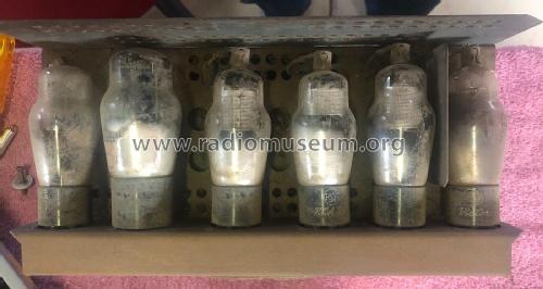
The Crosley Model 173 was manufactured in 1933. It is a 6-Valve superhet using 78 (RF), 78(Mixer),6B7(IF and Detector), 78 (1st Audio) and 43 as AF amp. Rectifier is a 25Z5. It covers two bands,approximately 500-1500kHz on Medium Wave and 1500 – 3100kHz on Short Wave.
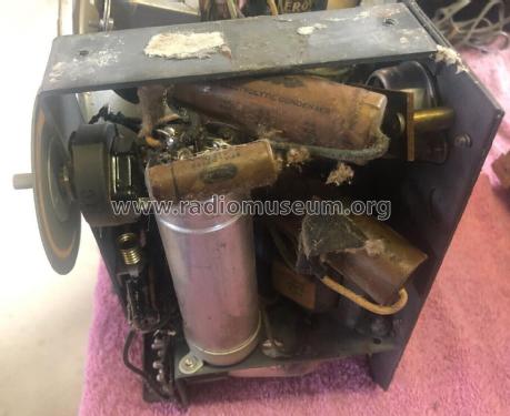
The owner wanted it to have good sound quality - and he wanted to show his son the valves glowing.The appearance of the electronics was not a consideration. Like most people, he wanted a repair NOT a restoration.
Preliminary
After nearly 80 years – quite a number of things had stopped working! There was no point in plugging the set into the mains and seeing if it would work, because a visual inspection showed that one valve was cracked open and a small coil had fallen apart. I never plug in to the mains straight away anyway - always bring the voltage up slowly using a Variac and isolation transformer. I don't have a valve tester with UX- bases, so I purchased a full set of valves, plus an extra 78. Any left over would be useful for future repairs.
The obviously broken valve was replaced and the small choke was repaired by soldering the broken  connection and covering the joint with laquer. The coil was reassembled round a brass screw. Finally, the assembly was checked.
Strategy
The strategy adopted would be to:
- Study the circuit diagram and notes carefully,
- Get the HT and power supply working,
- Work backwards from the audio to the RF stages get each stage working in turn,
- Finally, adjust/and align the set (or at least check the alignment).
When this strategy fails, it usually because psychologically the person doing the repairs doesn't want a particular part to be broken - and so - fails to test it. It is as if one has a "blind spot".
Applying Power
When power was gradually applied, there was no HT, and no filaments glowed either. Replacing the 25Z5 solved this problem and the set had the specified HT voltage. Checking the voltages as per the table in the repair data showed that several valves were not operating. These were replaced and the faulty components were thrown away. (I always throw away faulty parts immediately - otherwise you end up trying to use them again and waste a lot of time.) The top cap on the 6B7 fell off, so that was also replaced. I use a small screwdriver to prise the top caps off valves, placing it in the gap between the top cap and clip in order to avoid putting any strain on the wire soldered to the top cap.
Checking the Audio (Part 1)
The set was then slowly brought up to working voltage, but it remained silent. Placing a screwdriver tip on the grid of the 1st Audio stage did not produce a loud hum, confirming that these stages were not operating. The cathode resistor of the 43 was then checked and found to be open circuit. Replacing this did not help.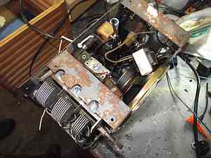
Putting a modern loudspeaker across the output transformer brought forth a small amount of sound. A check on the original speaker field coil revealed it to be open circuit. In the mean time, I realigned the set as well as I could. The set had a tendency to go into self-oscillation.
A check on the audio showed that the components did not agree with the circuit diagram. The set had a 3Meg resistor in series with (what I thought was) a 3Meg volume control. The circuit diagram showed a 500k Volume control - which I would have to purchase, since I didn't have any.
The original speaker field coil needed a mere 15000 turns of hair-fine wire, so I duly rewound it. (The hard part is the unwinding and counting the turns). The speaker then came to life, but really didn't sound too great compared to a modern speaker and the speaker cone was very brittle.(The original speaker could have been re-coned, at a price.) At this point, the set was working, but neither myself nor the owner were too enthralled by the sound quality, so I said I would have a think about it and we would give it another try early in January 2012.
Checking the Audio (Part 2)
In January the set was returned to me, and I couldn't believe how horrid the audio had become. The set had also become very “dead”. Clearly, the alignment hadn't survived the journey home and back, after realigning again I put a small dab of paint on all the trimmers.
In the mean time, I had managed to get a brand new permanent magnet speaker the same size as the original. It even had space on the back for mounting the output transformer! I also decided to return the volume control to that of the original circuit diagram. For some reason, I had a bit of difficulty getting a 470k log volume control with switch. Crosley had obviously made a modification involving a volume control having quite a high resistance. I checked the volume control I had removed and to my surprise it measured more than 30Meg. How it changed the volume level, I will never know. As a final touch, I added another large value electrolytic in parallel with the cathode by-pass capacitor of the 43, to give a more pleasing bass response.
RF Stage problems
The only remaining problem was a tendency for the RF stage to go into self-oscillation on a very short aerial – cured by placing a 27k resistor in parallel with the 1st RF coil on medium-wave. Re-positioning the wiring also helped solve this problem.
Rewiring Aesthetics
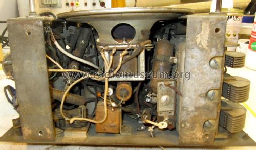
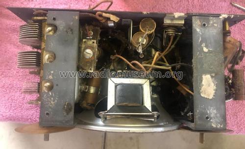
When re-wiring a radio of this age, nothing looks worse than modern vinyl covered wiring amongst the cotton covered rubber cables used in the original. It's possible to buy a woven sheath which can be put round the PVC cable to hide it. It also makes the wire about the same diameter as the original. It is possible to get the original type of cable from some American suppliers. The other problem is modern capacitors, which are about a tenth of the size of the original paper ones, and can look a bit silly. If you don't want to drill out the original paper tube and hide a modern cap inside, then the next best thing is to choose ones with a huge working voltage. Although these things don't matter to the owner - they mattered to me.
Alignment
I wasn't able to see any way to adjust the inductance of any of the RF and IF coils in the radio, so alignment was a compromise process with the radio tuned to somewhere near the high end of the tuning range. I used a small "hobby type" signal generator and oscilloscope connected to the detector. I simply aligned the IF to peak at the Intermediate frequency.

Final performance
As expected, the set was quite sensitive - able to produce good sound quality with an aerial consisting of a jumper lead about 300mm long. With an indoor aerial of 3m length, the set responded well, giving excellent audio quality and at last, both the owner and myself were happy.
Bryce Ringwood, 06.Apr.12


