Fiver 517, Cabinet 6K early
Crosley Radio Corp.; Cincinnati (OH)
- Country
- United States of America (USA)
- Manufacturer / Brand
- Crosley Radio Corp.; Cincinnati (OH)
- Year
- 1937
- Category
- Broadcast Receiver - or past WW2 Tuner
- Radiomuseum.org ID
- 73758
eBay item number:134414906534
eBay item number:134414906534

eBay item number:134414906534
eBay item number:134414906534
eBay item number:134414906534

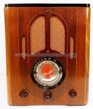
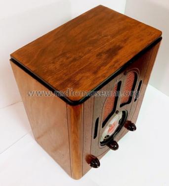
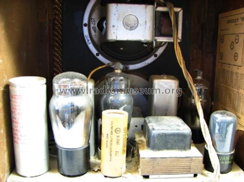
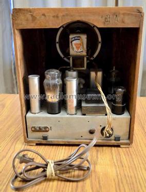
Cabinet 6K. eBay item number:134414906534.
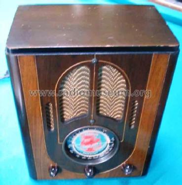
eBay seller ronsthe1.

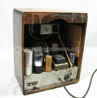
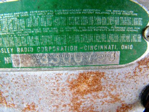
S/N 4019360 (early). eBay seller ronsthe1.

eBay seller ronsthe1.

from ebay
from ebay
from ebay
from ebay
from ebay

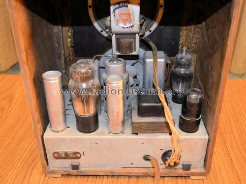
ebay seller watt58, item # 306017687056.
ebay seller watt58, item # 306017687056.
ebay seller watt58, item # 306017687056.
ebay seller watt58, item # 306017687056.


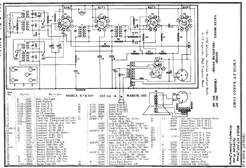
Click on the schematic thumbnail to request the schematic as a free document.
- Number of Tubes
- 5
- Main principle
- Superheterodyne (common); ZF/IF 455 kHz; 2 AF stage(s)
- Wave bands
- Broadcast and Short Wave (SW).
- Power type and voltage
- Alternating Current supply (AC) / 117 Volt
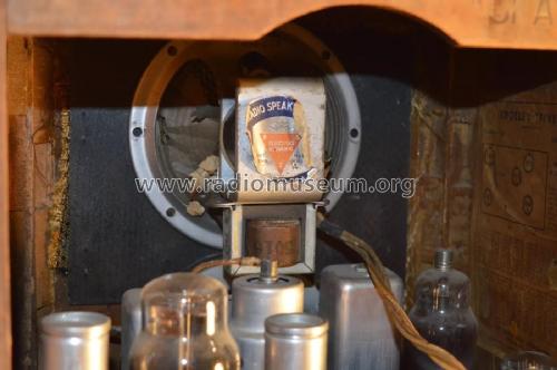
- Loudspeaker
- Electro Magnetic Dynamic LS (moving-coil with field excitation coil) / Ø 5 inch = 12.7 cm
- Power out
- 3.25 W (unknown quality)
- Material
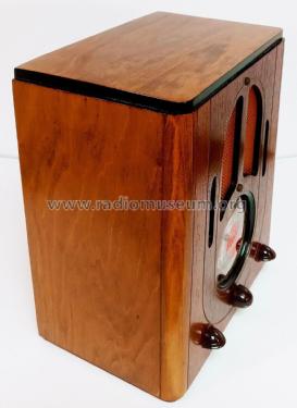
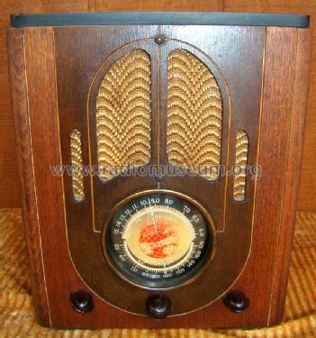
- Wooden case
- from Radiomuseum.org
- Model: Fiver 517, Cabinet 6K [early] - Crosley Radio Corp.;
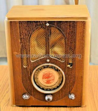
- Shape
- Tablemodel, Tombstone = decorative upright, not cathedral but can have rounded edges.
- Dimensions (WHD)
- 10.375 x 12.5 x 6.75 inch / 264 x 318 x 171 mm
- Notes
-
This model page will be the primary source of information for all the 517, 547, and 5517 family models and should be referenced on those related model pages.
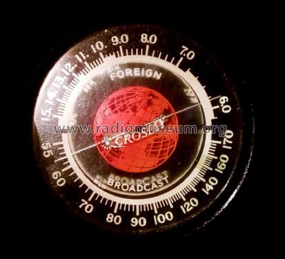
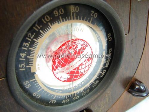
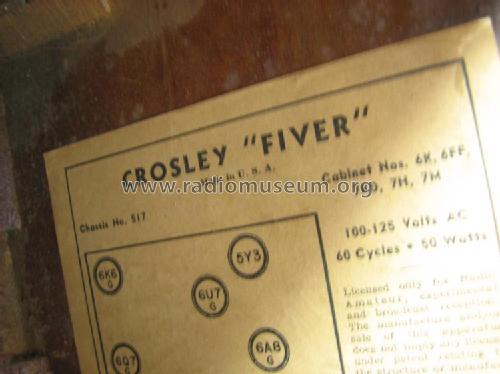
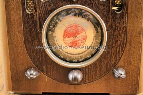
The Crosley "Fiver" family was introduced in 1937 with two models: 517 (early) and 547 (early), both with the same chassis schematic. The 547 model added the "Teletune" option, easily identified by the telephone-like escutcheon with telephone-like tuning. The early models are 517 below S/N 4032104 and 547 below S/N 4338751. The early model Dials had the Foreign band on top and the Broadcast band on the bottom. These models came in several different cabinets; tabletop and console.
In late 1937 or early 1938, they updated the schematic slightly and identified the models as 517 (late) and 547 (late), and added the 5517 model. The late models are 517 above S/N 4032103 and 547 above S/N 4338750; this update applies to all 5517 S/Ns. These models came in several different cabinets; tabletop and console.
Note that the 567 Chairside models were introduced at this later date and are schematically similar to the 517 (late) except the large filter capacitors were moved from the chassis top to the chassis bottom, perhaps for cabinet clearance issues. They have their own schematics, so they are not referenced here.
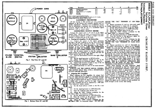
Some of these updates were:
- Added optional power transformers for 110 V, 50 Hz and 220 V, 50 Hz.
- Some models may have an added wave trap with a tunable frequency near the IF 455 kHz. This was added to eliminate interference from code stations operating near the IF frequency. This circuitry was located on the chassis bottom, next to the Antenna/Ground terminals.
- Some component/wiring changes to the volume and AVC circuitry.
- Late model Dials had the Broadcast band on the top and the Foreign band on the bottom.
Some of the visually identifiable differences between the models, early and late are shown in the following table.
Model Teletune Dial Bands (Top/Bottom)1 517 (early) N FN/BC 517 (late) N BC/FN 547 (early) Y FN/BC 547 (late) Y BC/FN 5517 N BC/FN 55172 Y BC/FN Notes 1 The two bands are printed on the top and bottom of the Dial. They were reversed
from early to late. The pointer is airplane style. FN=Foreign, BC=Broadcast.2 Documentation is unclear if the 5517 Teletune model has a different number,
so it is assumed to be 5517 for now.
- Price in first year of sale
- 19.99 USD
- Source of data
- Machine Age to Jet Age II
- Circuit diagram reference
- Rider's Perpetual, Volume 8 = 1937 and before
- Mentioned in
- Cathedral & Tombstone Radios (page 84.)
- Literature/Schematics (1)
- - - Manufacturers Literature (Crosley Broadcaster, April 15, 1937, page 6)
- Author
- Model page created by Steven Sostrom. See "Data change" for further contributors.
- Other Models
-
Here you find 1807 models, 1050 with images and 1301 with schematics for wireless sets etc. In French: TSF for Télégraphie sans fil.
All listed radios etc. from Crosley Radio Corp.; Cincinnati (OH)
Collections
The model Fiver is part of the collections of the following members.