Low-Frequency Radio Range Receiver 43B
Detrola; Detroit (MI)
- Country
- United States of America (USA)
- Manufacturer / Brand
- Detrola; Detroit (MI)
- Year
- 1940 ??
- Category
- Radio module post 1925 (not a part, not a key)
- Radiomuseum.org ID
- 304099

- Number of Tubes
- 5
- Main principle
- Superheterodyne (common)
- Wave bands
- Wave Bands given in the notes.
- Power type and voltage
- Storage Battery for all (e.g. for car radios and amateur radios) / 26 Volt
- Loudspeaker
- - For headphones or amp.
- Material
- Metal case
- from Radiomuseum.org
- Model: Low-Frequency Radio Range Receiver 43B - Detrola; Detroit MI
- Shape
- Chassis only or for «building in»
- Dimensions (WHD)
- 107 x 107 x 180 mm / 4.2 x 4.2 x 7.1 inch
- Notes
-
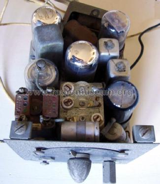
This is a very compact radio receiver to be used in small boats or aircraft as navigation aid to the low-frequency radio range standard. The receiver, made by Detrola, appears to be a 5-tube superheterodyne operating over a tuning range from 200 to 400 kHz. Commands on the front panel are just the volume control associated with the power supply switch and the tuning control knob with coaxial gear reduction driving the tuning pointer. A phone jack is on the left side.
The receiver works with 26.5 volts supply even for anodic voltage. Not needing a high-voltage vibrator-type power supply, this solution makes it possible to save space and increase the reliability. Tubes are: 6K7GT RF amplifier, 6SA7GT converter, 6SK7GT IF amplifier, 6SQ7GT/G detector and AF amplifier, 28D7 power audio amplifier.
The low-frequency radio range, also known as A-N radio range or four-course radio range, was one of the very early navigation systems. It was widely in use since 1929 and up to the sixties for marking both air and marine courses and guide aircraft or boats respectively to their airport or to the harbor. The system was based upon the emission of complementary Morse signals from an antenna system formed by two perpendicular Adcock antenna pairs. Four radiation lobs were generated, their intersections giving the wanted courses.
One Adcock pair was fed with a tone-modulated signal giving the ‘A’ Morse character, dot-dash, the second one emits the complementary ‘N’ character, dash-dot. When the pilot was straight in one of the four ranges, he could hear a continuous tone. Depending upon the course and the direction, if he moved to one side, he received the ‘N’ stream. On the contrary he could hear an ‘A’ stream when he moved to the opposite side.
- Author
- Model page created by Emilio Ciardiello. See "Data change" for further contributors.
- Other Models
-
Here you find 334 models, 195 with images and 291 with schematics for wireless sets etc. In French: TSF for Télégraphie sans fil.
All listed radios etc. from Detrola; Detroit (MI)
Collections
The model Low-Frequency Radio Range Receiver is part of the collections of the following members.