Capehart 34P10
Farnsworth Television & Radio Corp. - see also Capehart
- Country
- United States of America (USA)
- Manufacturer / Brand
- Farnsworth Television & Radio Corp. - see also Capehart
- Year
- 1948–1950
- Category
- Broadcast Receiver - or past WW2 Tuner
- Radiomuseum.org ID
- 40035
SAMS
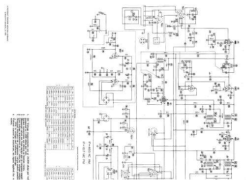
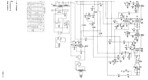
Click on the schematic thumbnail to request the schematic as a free document.
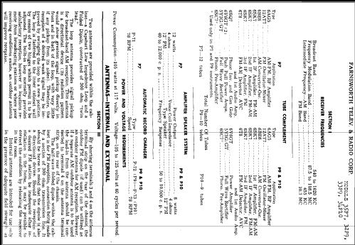
- Number of Tubes
- 10
- Main principle
- Superhet with RF-stage; ZF/IF 455/10700 kHz
- Tuned circuits
- 9 AM circuit(s) 11 FM circuit(s)
- Wave bands
- Broadcast (BC) and FM or UHF.
- Details
- Changer (Record changer)
- Power type and voltage
- Alternating Current supply (AC) / 105 - 125 Volt
- Loudspeaker
- Permanent Magnet Dynamic (PDyn) Loudspeaker (moving coil) / Ø 11.875 inch = 30.2 cm
- Power out
- 8 W (unknown quality)
- Material
- Wooden case
- from Radiomuseum.org
- Model: Capehart 34P10 - Farnsworth Television & Radio
- Shape
- Console with any shape - in general
- Notes
-
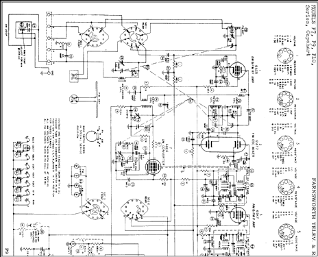
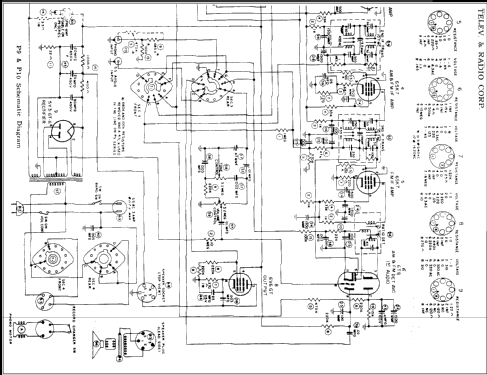
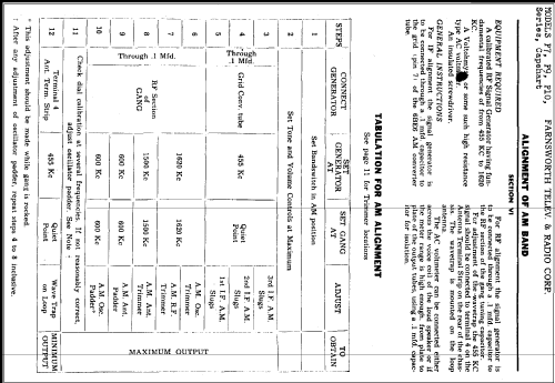
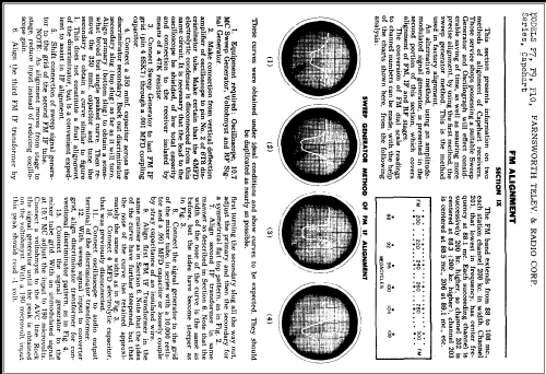
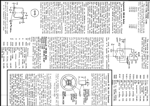
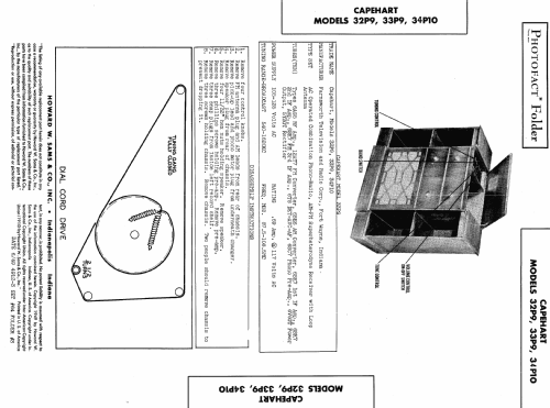
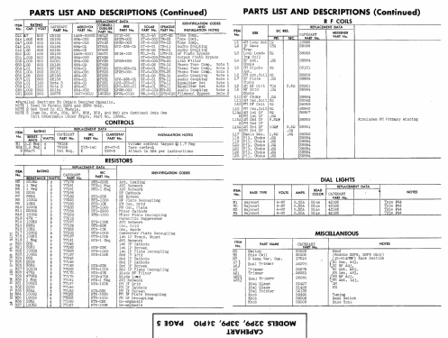
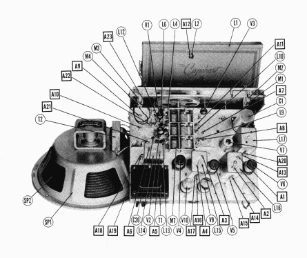
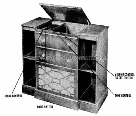
According to SAMS Photofact Folder Date 6-49, 4912-3, set 64, folder 3, the following Capehart models, made by Farnsworth Television and Radio Corp., fort Wayne, Indiana use the same chassis: 32P9, 33P9 and 34P10. The Record Changer here is a P-73 and there is a built in AM loop antenna. Model 34P10 is without the bias cell. We don't know the name of the cabinet yet. See here the "Common information for the Capehart model pages for the 1930s and 1940s".
- External source of data
- Ernst Erb
- Source of data
- The Radio Collector's Directory and Price Guide 1921 - 1965
- Circuit diagram reference
- Rider's Perpetual, Volume 19 = 1949 and before
- Literature/Schematics (1)
- Photofact Folder, Howard W. SAMS (Date 6-49, 4912-3, set 64, folder 3)
- Other Models
-
Here you find 400 models, 284 with images and 327 with schematics for wireless sets etc. In French: TSF for Télégraphie sans fil.
All listed radios etc. from Farnsworth Television & Radio Corp. - see also Capehart