Capehart 35P7 Ch= P-7
Farnsworth Television & Radio Corp. - see also Capehart
- Country
- United States of America (USA)
- Manufacturer / Brand
- Farnsworth Television & Radio Corp. - see also Capehart
- Year
- 1948–1951
- Category
- Broadcast Receiver - or past WW2 Tuner
- Radiomuseum.org ID
- 40036
von Josh Fisher
SAMS
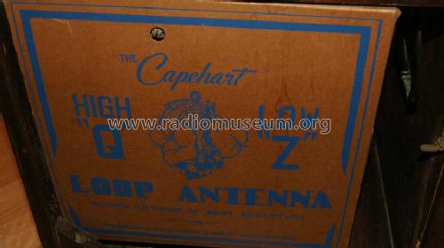
Capehart 35P7 Antenna
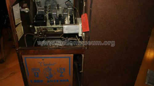
Capehart 35P7 Back
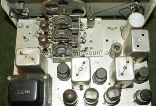
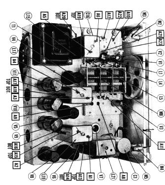
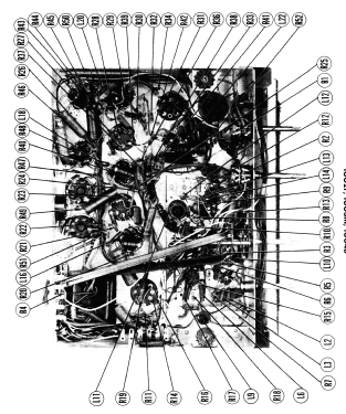
Capehart 35P7 Chassis Top
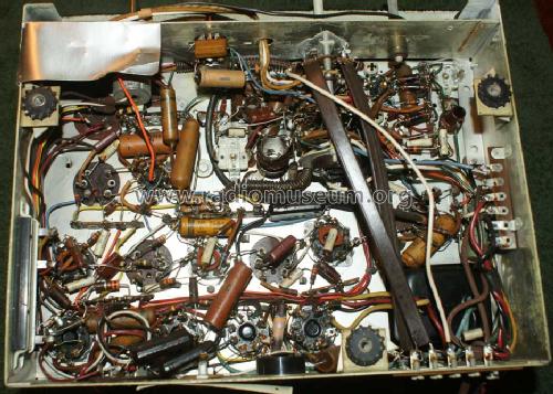
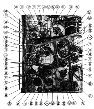
Capehart 35P7 Chassis Bottom
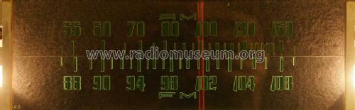
Capehart 35P7 Scale
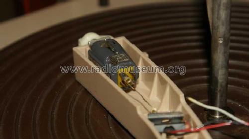
Capehart 35P7 Phonograph Pickup
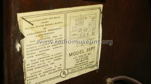
USA_Farnsworth_capehart_35P7_Type_Label
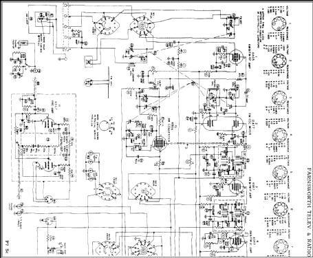
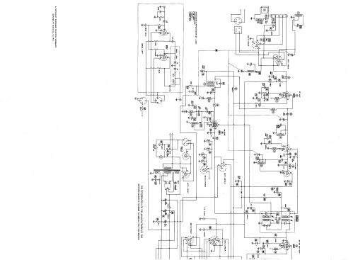
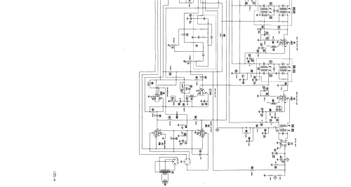
Click on the schematic thumbnail to request the schematic as a free document.
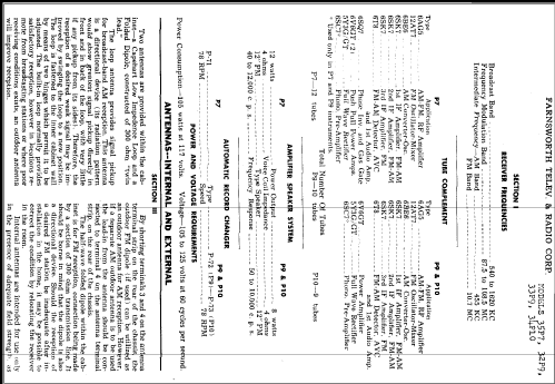
- Number of Tubes
- 12
- Main principle
- Superhet with RF-stage; ZF/IF 455/10700 kHz
- Tuned circuits
- 9 AM circuit(s) 11 FM circuit(s)
- Wave bands
- Broadcast (BC) and FM or UHF.
- Details
- Changer (Record changer)
- Power type and voltage
- Alternating Current supply (AC) / 60 Hz, 117V = 110 -120 Volt
- Loudspeaker
- Permanent Magnet Dynamic (PDyn) Loudspeaker (moving coil) / Ø 11.875 inch = 30.2 cm
- Material
- Wooden case
- from Radiomuseum.org
- Model: Capehart 35P7 Ch= P-7 - Farnsworth Television & Radio
- Shape
- Console with any shape - in general
- Notes
-
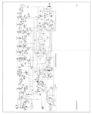
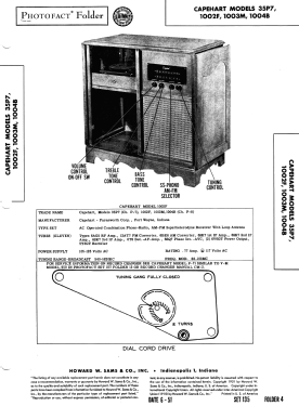
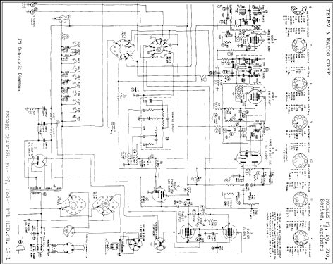
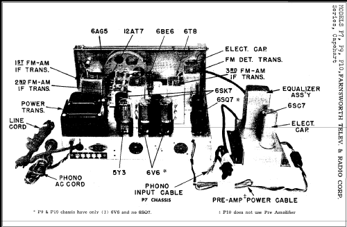
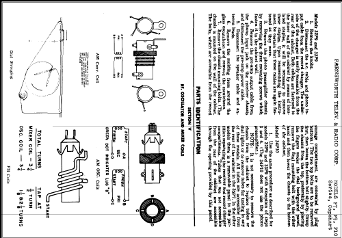
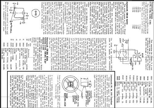
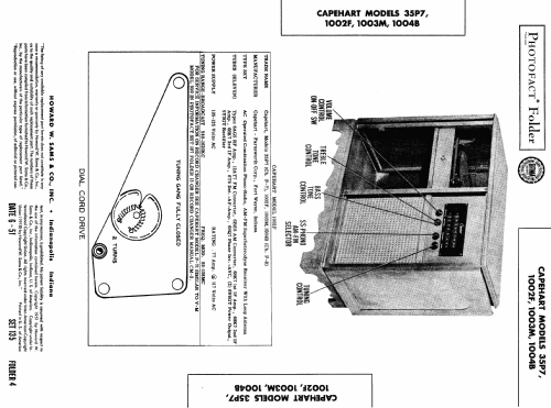
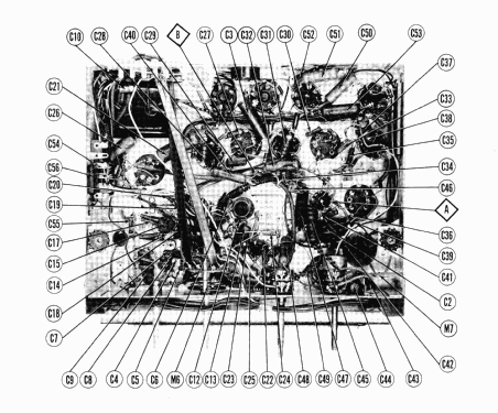
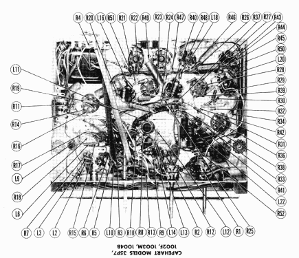
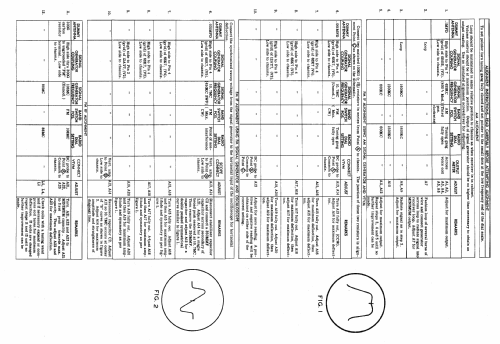
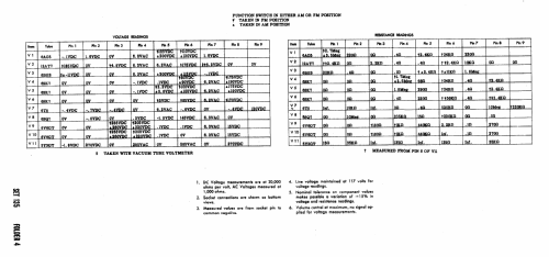
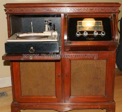
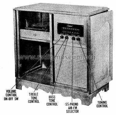
Capehart model 35P7 is an AC operated combination phono-radio, AM-FM superheterodyne receiver with loop antenna.
According to SAMS Photofact Date 6-51, set 135, folder 4, the following Capehart models, made by Farnsworth Television and Radio Corp., fort Wayne, Indiana use the following chassis: 35P7 = chassis P-7 (including tube 6SC7 for the bias cell), 1002F, 1003M and 1004B = chassis P-8 with a different loop antenna and treble tone control instead of bass tone control. The Record Changer here is a P-71 and there is a built in AM loop antenna.
See here the "Common information for the Capehart model pages for the 1930s and 1940s". Here the cabinet style is missing.
- External source of data
- Ernst Erb
- Circuit diagram reference
- Rider's Perpetual, Volume 19 = 1949 and before
- Literature/Schematics (1)
- Photofact Folder, Howard W. SAMS (Date 6-1951, Set 135, Folder 4)
- Other Models
-
Here you find 400 models, 284 with images and 327 with schematics for wireless sets etc. In French: TSF for Télégraphie sans fil.
All listed radios etc. from Farnsworth Television & Radio Corp. - see also Capehart
Collections
The model Capehart 35P7 is part of the collections of the following members.