ET-651RDZ Ch= 171
Farnsworth Television & Radio Corp. - see also Capehart
- Country
- United States of America (USA)
- Manufacturer / Brand
- Farnsworth Television & Radio Corp. - see also Capehart
- Year
- 1947 ?

- Category
- Broadcast Receiver - or past WW2 Tuner
- Radiomuseum.org ID
- 40188
Click on the schematic thumbnail to request the schematic as a free document.
- Number of Tubes
- 5
- Main principle
- Superheterodyne (common); ZF/IF 455 kHz; 2 AF stage(s)
- Tuned circuits
- 6 AM circuit(s)
- Wave bands
- Broadcast plus 2 Short Wave bands.
- Power type and voltage
- Alternating Current supply (AC) / 30 Watts, 5 taps: 105; 120; 145; 190; 220 Volt
- Loudspeaker
- Permanent Magnet Dynamic (PDyn) Loudspeaker (moving coil) / Ø 6 inch = 15.2 cm
- from Radiomuseum.org
- Model: ET-651RDZ Ch= 171 - Farnsworth Television & Radio
- Shape
- Tablemodel, with any shape - general.
- Notes
-
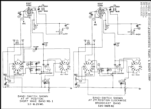
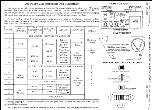
Rider's pages Farnsworth 18-1 to 18-5 show the same schematic for the models ET-650BRZ, ET-651BKZ, ET-651BUZ and ET-651RDZ, Chassis 171. The bands are broadcast 535 to 1605 kHz, SW1 3.3 to 8.25 MHz and SW2 8.6 to 21.8 MHz. See alos this text for Capehart or the link there for more information.
- External source of data
- Ernst Erb
- Circuit diagram reference
- Rider's Perpetual, Volume 18 = 1949 and before
- Other Models
-
Here you find 400 models, 284 with images and 327 with schematics for wireless sets etc. In French: TSF for Télégraphie sans fil.
All listed radios etc. from Farnsworth Television & Radio Corp. - see also Capehart


