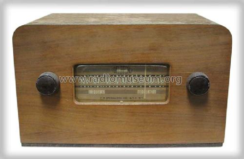
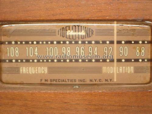
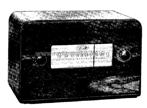
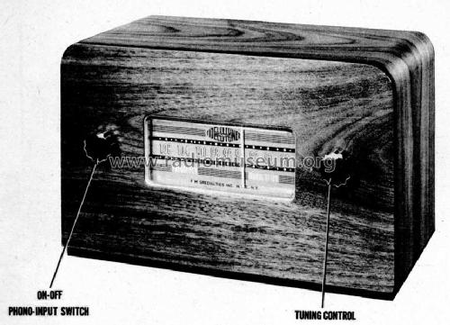
Edwards Fidelotuner
F.M. Specialties, Inc.; New York; also: Edwards F-M Radio Corp. NY
- Country
- United States of America (USA)
- Manufacturer / Brand
- F.M. Specialties, Inc.; New York; also: Edwards F-M Radio Corp. NY
- Year
- 1948 ?
- Category
- Broadcast Receiver - or past WW2 Tuner
- Radiomuseum.org ID
- 39282
Click on the schematic thumbnail to request the schematic as a free document.
- Number of Tubes
- 5
- Number of Transistors
- Semiconductors
- Selenium-Rectifier
- Main principle
- Superheterodyne (common); ZF/IF 10700 kHz
- Tuned circuits
- 10 FM circuit(s)
- Wave bands
- FM Broadcast Band Only
- Power type and voltage
- Alternating Current supply (AC) / 105 - 130 Volt
- Loudspeaker
- - For headphones or amp.
- Material
- Wooden case
- from Radiomuseum.org
- Model: Edwards Fidelotuner - F.M. Specialties, Inc.; New
- Shape
- Tablemodel without push buttons, Mantel/Midget/Compact up to 14
- Dimensions (WHD)
- 11 x 6.75 x 5.75 inch / 279 x 171 x 146 mm
- Notes
-
Edwards Fidelotuner employs transmission line tuning for antenna and oscillator circuit.
- External source of data
- Ernst Erb
- Circuit diagram reference
- Rider's Perpetual, Volume 17 = 1948 and before
- Literature/Schematics (4)
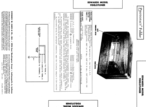
- Photofact Folder, Howard W. SAMS (Set 33, Date 2/48, Folder 483-4)
- Other Models
-
Here you find 3 models, 1 with images and 2 with schematics for wireless sets etc. In French: TSF for Télégraphie sans fil.
All listed radios etc. from F.M. Specialties, Inc.; New York; also: Edwards F-M Radio Corp. NY
Forum contributions about this model: F.M. Specialties,: Edwards Fidelotuner
Threads: 1 | Posts: 1
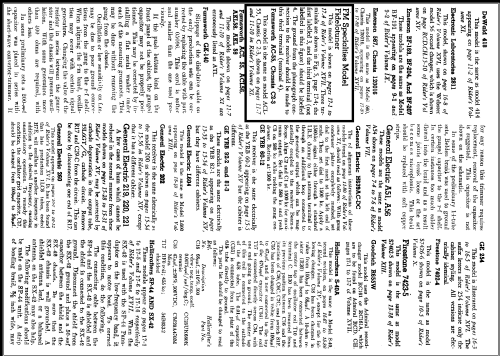
In "Rider, J.F.; Ulsan, S.D.: FM Transmission and Reception, 2nd ed., Rider, 1951" findet sich eine Beschreibung des "Edwards Fidelotuner". In anderen Literaturstellen wird das Gerät auch als "Fidelituner" bezeichnet. ("i" statt "o" scheint aber falsch zu sein.)
The Edwards Fidelotuner
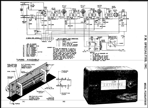
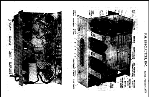
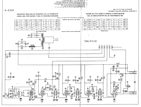
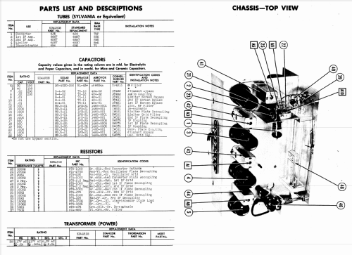
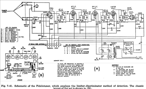
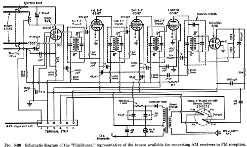
This f‑m tuner4 employs the limiter‑discriminator method of detection. The complete schematic for this tuner is illustrated in Fig. 7‑41 (A), and a drawing of the top chassis layout is shown in Fig. 7‑41 (B).
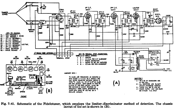
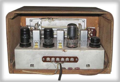
Five tubes are employed in the unit, with three 6SH7 sharp‑cutoff pentodes used as the first and second i‑f amplifiers and also as the limiter. The discriminator uses the duo‑diode 6H6 tube, and the 6J6 miniature duo‑triode is used as the converter. Note that no separate r‑f stage is employed, even though the tuner uses the limiter‑discriminator detector network. The reason for this is that the signal‑to‑noise ratio of the set is high, and the signal input to the limiter is sufficiently great to give satisfactory performance.
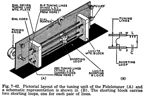
A few interesting features about this tuner warrant special mention, and the most interesting is the method of tuning. The tuning in this unit is inductive, but does not involve any permeability tuning. Open‑wire parallel transmission lines are used for varying the inductance of the r‑f input and oscillator section of the converter tube. Consequently, this type of tuning is called transmission line tuning. The variation in inductance is obtained by running a shorting bar along the parallel line, thus changing the inductance offered by the changing length of each line. A schematic representation of this tuning system is shown in the upper left part of the diagram of Fig. 7‑41 (A), and its physical layout on the chassis is seen in Fig. 7‑41 (B). To show exactly how this tuning unit works, a pictorial view of it, showing both the oscillator and r‑f tuning lines is illustrated in Fig. 7‑42 (A), and a schematic representation of how the tuning lines form the tank circuit is illustrated in Fig. 7‑42 (B).
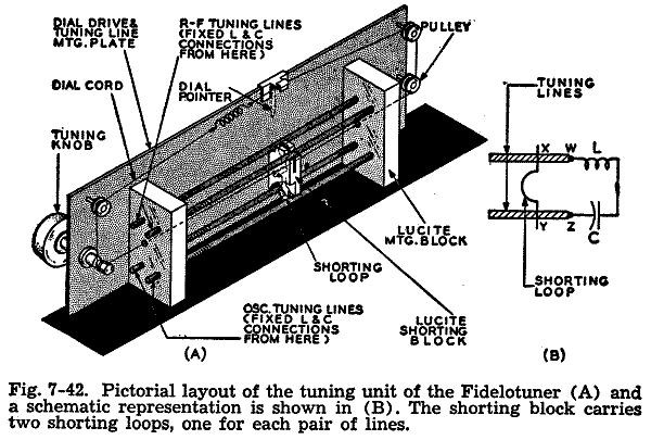
Since the frequencies involved are quite high, the inductive and capacitive values that form the r‑f or oscillator tank circuits are very .small. Thus, it is possible to use the difference in inductance in the varying length of transmission line as a means of high‑frequency tuning. The actual formation of the oscillator and r‑f tank circuits uses a fixed inductance and capacitance, which are connected together at one end, in conjunction with a transmission line in each case. From the other ends of these components, the two transmission line leads are connected. This is indicated in Figs. 7‑41 (A) and 7‑42 (B). A metal shorting loop is rigidly placed across each set of lines, and the position of this loop on the lines determines how much extra inductance is added to the tank circuit because the shorting loop completes the tank circuit.The schematic of Fig. 7‑42 (B) will make this somewhat clearer. The inductor L and capacitor C represent the fixed quantities in the circuit and are connected together as shown. Let us assume that the shorting loop is at the position indicated. To complete the tank circuit, the current must travel through one part of the line, then through the shorting loop, and finally through the other part of the line back to the circuit. It can travel from L, then to points W, X, Y, and Z and then to capaeitor C; or it can go from C in the direction of Z, Y, X, W, and then to inductor L to complete the circuit. It is the added inductance of the parts of the line from W to X and from Y to Z, plus that of the shorting loop in conjunction with the distributed capacitance of the line parts, which determines the final resonant frequency of the tank circuit. The lengths W to X and Z to Y are equal due to the mechanical nature of the system. The shorting loops are very thin phosphor bronze springs rigidly mounted in a lucite block, which in turn is connected to the dial cord and pulley arrangement for the proper tuning of the set. This is seen from Fig. 7‑42 (A). Both the oscillator and r‑f shorting loop are placed in the same shorting block, so that they are effectively ganged together and are variable as one upon tuning of the unit. The r‑f and oscillator lines are spaced far enough apart, so that no serious interaction between these circuits is possible. The lines are all made of hardened brass tubing 51/2 inches long and 1/8 inch in diameter, and they are covered with a thin layer of silver plate. The shorting loop makes a hair line contact with the lines, and this contact is maintained in a rigid state due to the high spring tension of the phosphor bronze and the shape of the loop. The lines themselves are fixed in position on two lucite mounting blocks f astened to a mounting plate.
Although there have been other types of inductive tuning circuits, we believe the type illustrated here to be of a unique yet very simple design, with which proper tuning can be obtained with the least amount of trouble.
There are two other interesting features to this tuner. One is that a duo‑triode 6J6 miniature tube is used as a converter, in which one triode section serves as the mixer and the other as the oscillator. Although it has not been mentioned previously, two triodes used for a system of frequency conversion have one of the highest, if not the highest, signal‑to‑noise ratios among converter systems. This high signal‑to‑noise ratio obviates the need for an r‑f stage to increase the signal input.
The other interesting thing is that the oscillator plate current flows through the transmission line and shorting loop as seen in Fig. 7‑41 (A). This current flow is a good reason why the loop contact to the lines must be tight.
The i‑f and discriminator transformers are of the special kind that use magnetic shielding in conjunction with permeability tuning, as discussed in the section dealing with the i‑f system and Fig. 7‑12.
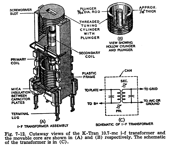
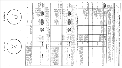
The terminal strip shown in Fig. 7‑41 (A) is on the back of the chassis, and it affords a quick means of alignment as well as a fast and easy method of connecting the tuner to an a‑m radio or amplifier. The meter method of aligning the i.f.'s and discriminator is also indicated in Fig. 7‑41. At the end of chapter 8, the factory alignment procedure for this tuner will be found, using a combined meter and visual method.
4 Manufactured by FM Specialties Inc., of New York, N. Y., under the brand name of "Edwards Fidelotuner."
MfG DR
Dietmar Rudolph † 6.1.22, 31.Jul.13
