- Country
- United States of America (USA)
- Manufacturer / Brand
- Freed-Eisemann Radio Corp.; New York, NY
- Year
- 1923/1924
- Category
- Broadcast Receiver - or past WW2 Tuner
- Radiomuseum.org ID
- 25423
Click on the schematic thumbnail to request the schematic as a free document.
- Number of Tubes
- 5
- Main principle
- TRF without regeneration; 2 AF stage(s); Neutrodyne
- Tuned circuits
- 3 AM circuit(s)
- Wave bands
- Broadcast only (MW).
- Power type and voltage
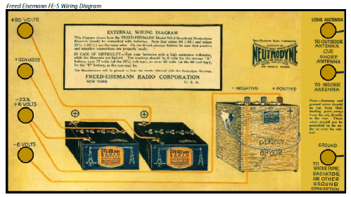
- Storage and/or dry batteries / 6 & 2 x 45 Volt
- Loudspeaker
- - For headphones or amp.
- Material
- Wooden case
- from Radiomuseum.org
- Model: NR-5 - Freed-Eisemann Radio Corp.;
- Shape
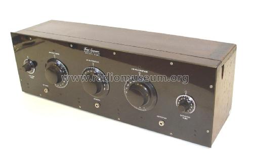
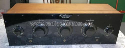
- Tablemodel, low profile (big size).
- Dimensions (WHD)
- 28 x 9 x 8 inch / 711 x 229 x 203 mm
- Notes
-
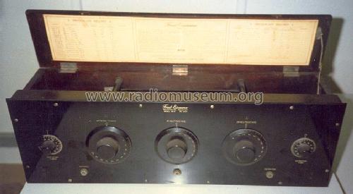
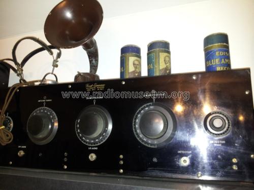
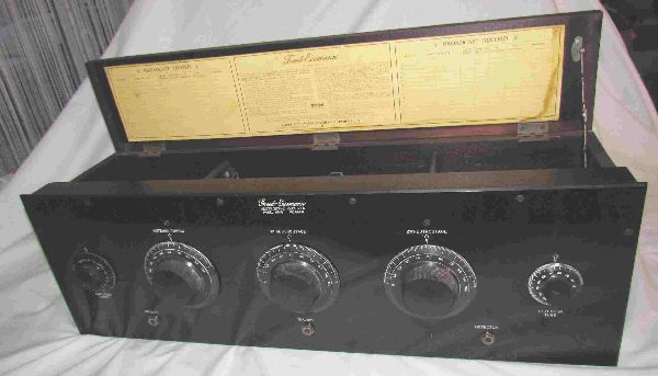
The Freed Eisemann NR-5 is a battery operated 5 tube BC band receiver. It was the first Neutrodyne offered from Freed-Eisemann (April 1923). The NR-6 followed in October 1924 at the same price. The original tube compliment recommended by the manufacturer was UV201A tubes in all positions.
The "Freed-Eisemann Dealer Catalog 1924" lists the models NR-5 (from April 1923), NR-6, NR-12, NR-20, NR-215, NR-400, Speaker FE-50 for models NR-5, NR-6 and NR-20, Speaker Console FE-150 matching NR-20, and FE-5C.
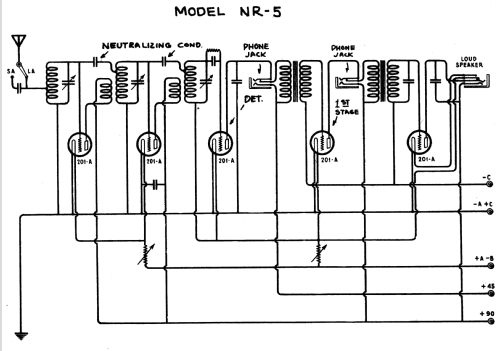
Two different radio's were closely examined and the published schematics did not match these two radio's. The published schematics show a C battery, but the actual radio's have no means to connect a C battery. The published schematics show the first 2 tube filaments controlled by a reostat and the last 3 tube filaments controlled by another reostat, but the actual radio's have 1 reostat for the detector tube filament and the other reostat controlling the remaining 4 tube filaments (which also matches the front panel engraving for the controls, which are "DETECTOR TUBE" and "AMPLIFIER TUBES"). There are other small differences, such as no capacitor across the speaker output jack. A schematic was made from the actual radio's and was uploaded to this model.
Receiver sensitivity is around -55 dBm over the band from 600 KHz to 1400 KHz with a very good signal to noise ratio of more than 10 dB (measured at 1st audio output with Rohde & Schwarz SM300 RF signal generator and an adapter for long wire antenna impedance; 2nd audio output can give more gain but introduce more distortions in the loudspeaker).
The signal goes in the noise level at around – 73 dBm. At 550 KHz the sensitivity is around -45 dBm with a good signal to noise ratio, and noise level is around – 63 dBm. From 600 KHz is stable at around -55 dBm.
Additional reference:
Literature/Schematics (5): The Spectrum Monitor, Dec. 2022, article titled "The Neutrodyne Patent and the Freed-Eisemann NR-5", pages 12-16. Summary: The early NR-5, complete with the long terminals protruding through the back of the chassis appears to be nearly identical to the original Neutrodyne introduced by Louis Alan Hazeltine at the Radio Club of America on March 23, 1923. It was built by Joseph Freed of Freed-Eisemann, pictured alongside of Hazeltine in the photo in Radio-World magazine March 24, 1923.
- Net weight (2.2 lb = 1 kg)
- 10 kg / 22 lb 0.4 oz (22.026 lb)
- Price in first year of sale
- 150.00 $
- Source of data
- Radio Manufacturers of the 1920's, Vol. 2
- Circuit diagram reference
- Rider's Perpetual, Volume 1 = 1931/1934 (for 1919-1931)
- Mentioned in
- Radio Collector`s Guide 1921-1932
- Literature/Schematics (1)
- Le Guide du Collectionneur TSF Biraud/Foster, Vol. I (page 168)
- Literature/Schematics (2)
- Collector's Guide to Antique Radios (7th Edition) (Radio Broadcast, Sep. 1923, p. 441)
- Literature/Schematics (3)
- Gernsback Official Radio Service Manual (Volume 1, 1930 Page 166A)
- Literature/Schematics (4)
- Rider's Perpetual, Volume 1 = 1931/1934 (1919 to 1931) (Riders (Freed) Page 1-1)
- Other Models
-
Here you find 205 models, 106 with images and 128 with schematics for wireless sets etc. In French: TSF for Télégraphie sans fil.
All listed radios etc. from Freed-Eisemann Radio Corp.; New York, NY
Collections
The model NR-5 is part of the collections of the following members.
- Ferit Akalin (TR)
- Gian-Fausto Balestra (CH)
- Walter Barteczek (D)
- Kenneth Carr (USA)
- Bob Deyoe (USA)
- Ernst Erb (CH)
- Markus Glaser (D)
- Michael Kolb (D)
- Carlos Romualdo Landi (RA)
- Roberto Montalto (I)
- Musée des Radios Museum (CH)
- Rich Post (USA)
- Manfred Rathgeb (D)
- Jeffrey Rehkopf (USA)
- Michael Sawyer (USA)
- Wilhelm Siepe (D)
- Serioja Tatu (CDN)
- Antonio Varrica (I)
- Hartmut Völler (D)
Museums
The model NR-5 can be seen in the following museums.
Forum contributions about this model: Freed-Eisemann Radio: NR-5
Threads: 8 | Posts: 18
Je voudrais soulever d’abord dans cet article le rôle de la petite batterie C, qui parfois était omise par le constructeur lui-même au début des années 1920. En deuxième lieu les performances techniques RF et AF, mesures sur un banc d’essais sont présentées.
Attachments
Serioja Tatu, 15.Nov.24
To whom it may concern, my name is Alan Bidwell and I am a member if the AVRS (Australian Vintage Radio Society) I regularly contribute articles to the club magazine, I am seeking permission to insert a copy of the Tuning Instructions as seen in the photos of the Freed Eisemann NR-5 . I will add a short note in the article discussing the efforts required in tuning a radio 100 years ago and now with the advent of voice activated radio tuning etc.
Regards
Alan Bidwell
Alan Bidwell, 16.Aug.23
There is an article in Popular Radio September 1925 page 243 titled "Your Ready Made Receiver" By S. Gordon Taylor covering these Freed Eisemann receivers. Copies are available on the americanradiohistory.com website.
Peter
Peter Scott, 07.Dec.19
I have two of these radios and here are some observations. There must be earlier and later models.
As noted on this forum, one model does not match the published schematic. This model has studs for the wiring on the back of the radio, with no hook-up for a C battery. I have one of those and the re-drawn schematic matches fine. This radio says "Broadcast Receiver" on the front panel and has the original, gold painted Freed-Eisemann transformers, although they are open in the secondaries.
The second version I have (later version?) has the wiring for the batteries already attached, along with the wiring for the C battery. This radio matches exactly the original schematic. There are no studs on the back for wiring hook-up. The back of the radio shows where a cover was put over the holes, with modified labels for the antenna hook-up.
I have noticed 3 different instruction labels:
1. All black print, with no comments about the detector tube found on other versions.
2. Black print with an underlined comment to use only a 201A in the detector, no matter what anyone else says. Also text in red print warning ablut how to hook up the batteries. (this is on the first version I mentioned above).
3. All black pring, with the comment to use only a 201A in the detector, but without the red print about battery hook-up. The cable is already attached and I am guessing that the wires had labels for the battery.
Jeffrey Rehkopf, 13.May.15
ein Nr.5 , den ich aus USA gekauft habe steht zur Restauration an. 371€ + 19%MWST.
Das war der Anlieferzustand:
.jpg)
.jpg)
Ergänzend zu den technischen Daten im Modell: Mahagony-Holzgehäuse
Originalröhrensatz wäre: 5 x UV201A bestückt war 4 x UX201A und UX301A
Restaurationszeit: 12 Wochen
Befund: ordentlicher Allgemeinzustand
losgerissener Audioübertrager zerschlägt während des Transports die Röhre UX201A
Röhrensockel zerbrochen
Rückwandbeschriftung im schlechten Zustand
Beschriftung von Frontplatte und Reglerknöpfen abgenutzt
1 falscher Drehknopf
1 Heizregler hat Unterbrechung
Röhrenprüfung: 3 x UX201A mit guten Werten, je eine UX201A mit Heizfadenbruch
eine mit Glasbruch
Zusätzliche Materialkosten: Ersatzröhre 2 x UX201A je 17€ und Ersatz für Heizregler 12€
Draht und Spulenkörper für 1 Audioübertrager 35€
Restauration Holzgehäuse 110€ insgesamt 191€
Alle Angaben in diesem Bericht beziehen sich auf den Schaltplan im Anhang.
Bei der Überprüfung und Vergleich mit dem Modell gespeicherten Schaltplan ergaben sich erhebliche Unterschiede. Die Verdrahtung stimmt nicht dem Schaltplan überein.
- Schaltplan zeigt eine Gitterbatterie und die Anschlüsse C- und C+
- Die Heizregler R3 und R2 sind anders verdrahtet-
R3 dient zum Abgleich der Batteriespannung 6V,
regelt gemeinsam die Röhren V1, V2, V4 und V5
R2 regelt nur die Heizspannung für die Röhre V3 - Kondensatoren an der Anode von V5 fehlt
- Zum Austesten mit externem Lautsprecher - 2kOhm- Anschluss über 2nd Audio
- Testen über Dtektor-Anschluss mit 2kOhm Kopfhörer- das Einstecken unterbricht die
Heizung der Röhe T4
diese Umstände brachten Verwirrung und Unsicherheit mit sich, was ist richtig und wie sah das Radio im Auslieferzustand einmal aus.
Deshalb habe ich mich an John Kusching gewandt, der auch einen Nr.5 hat. Im Detail haben wir alles überprüft und Schaltungsdetails und Bilder ausgetauscht. Es stellte sich dabei heraus, dass beide Radios gleich sind. Anhand der recherchierten Fakten wurde von John Kusching ein neuer Schaltplan erstellt.
Heizregler Restauration: Der Drahtwickel war mehrfach unterbrochen. Ein Original ersatzteil war nicht zu beschaffen.
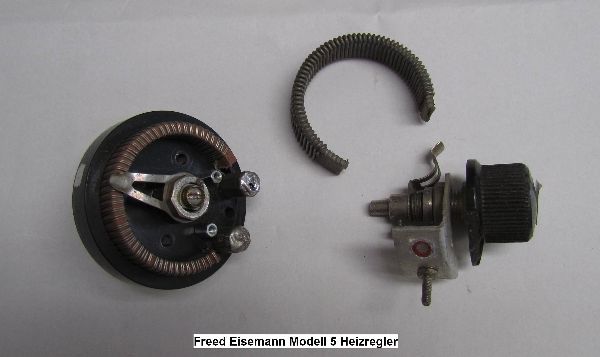
In der Bildmitte ist das Originalsegment zu sehen. Das komplette Drahtwickelsegment von R3 wurde herausgelöst und durch einen anderen Darhtwickel mit 2 Ohm von einem anderen Heizregler ersetzt. 2 neue Anschläge wurden eingebaut. Achse und Schleiffeder blieben vom Original erhalten.
Audioübertrager:
Damit die Originalübertrager zumindest vom Aussehen her unverändert bleiben, wurden beide Spulen neu gewickelt. Bei der Fabrikation wurden diese Spulen ohne Spulenkörper mit Wachsmantel hergestellt. Die Versuche –Bewickeln nur mit den Holztellern als Begrenzung- sind alle gescheitert. Beim Herauslösen entstanden Drahtbrüche. Deshalb habe ich Spulenkörper aus stabiler Pappe hergestellt. Die Pappe wurde mit verdünntem Kaltleim bestrichen, damit der Spulenkörper formstabil ist. Eingespannt mit den Holztellern hat man eine stabile Vorrichtung zum Wickeln. Die Windungen wurden alle 3 Lagen mit Folie isoliert. Zusätzlich wurde jede neue Lage mit Plastikspray isoliert und gleichzeitig verklebt.
Der Original Freed Eisemann Übertrager ist mit 1:8 angegeben. Man misst 1100 / 8600Ohm – und eine Drahtstärke von 0,04Cul. – Das Widerstandverhältnis beträgt 7,8, hochgerechnet auf die Windungszahlen kommt man auf ergibt eine Spannungsübersetzung von ca.1:5.
Um sicher zu gehen wurde das Radio mit 2 Ersatzübertragern 1:4 getestet. Das Radio spielt mit guten Röhren sehr laut, also 1:4 genügt für einen gute Empfangsleistung.
Meine Wickelmaschine kann 0,04 Cul nicht wickeln. Unter der maximalen Ausnützung des Wickelraumes wurden die Spulenkörper bewickelt.
Audioübertrager T4 1:4 primär 3400 Windungen 1413 Ohm mit 0,063Cul
und sekundär 13600 Windungen 7790 Ohm mit 0,063Cul
T5 1:3 primär 4000 Windungen 1200 Ohm mit 0,07Cul
und sekundär 12000 Windungen 4700 Ohm mit 0,063Cul
Oben sind die Originalspulen mit dem Wachsmantel zu sehen, rechts der aus Pappe hergestellten Spulenkörper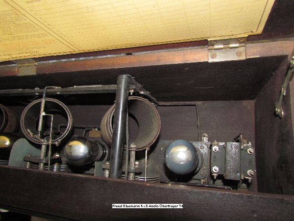
Übertrager T4 vor der Restauration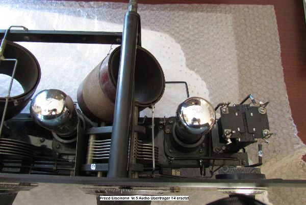
Übertrager T4 nach der Restauration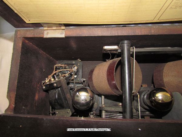
Übertrager T5 vor der Restauration
Übertrager T5 nach der Restauration
Die Anschlüsse der Profildrähte blieben unverändert. T4 und T5 sind nicht baugleich.
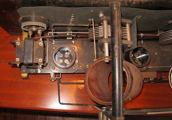
T5 in John Kuschings Radio
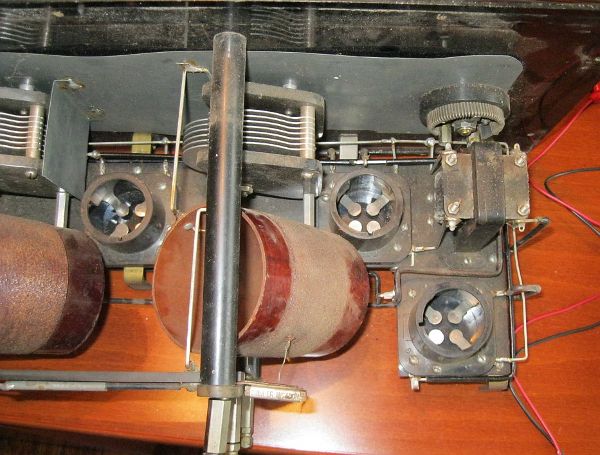
T4 in John Kusching Radio


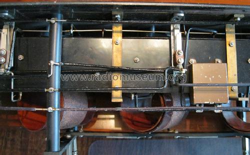
Verdrahtung im Detektor- und Audiobereich- die Kontaktierung der Klinkenbuchsen ist im Schaltplan ersichtlich.
Der Röhrensockel wurde aus dem Bruchstücken zusammengesetzt und mit 2 Komponenten Kleber Endfest 300 geklebt. Die Bruchstellen reinigen und um den Sockel einen stabile Teflonfolie (kleberabweisend) herumwickeln und mit Draht festgezurren. Nach einem Tag wird alles abgelöst und versäubert.
Koppelkondensatoren: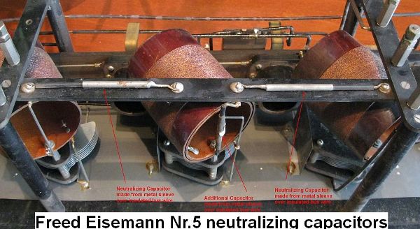

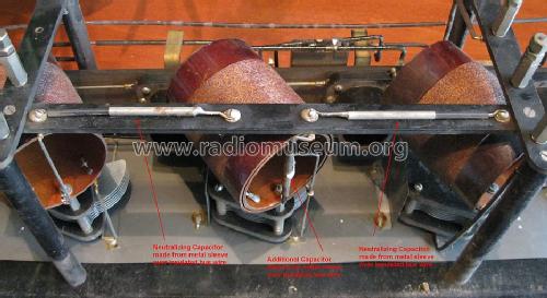
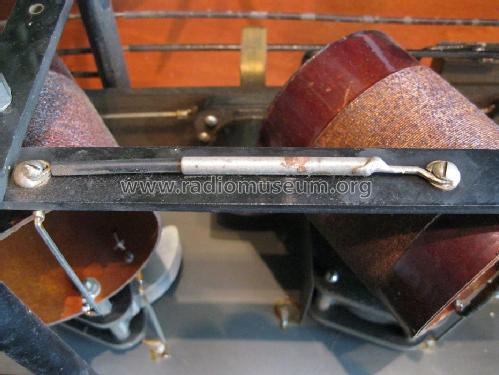
Die Koppelkondensatoren, ca. 10pF, bestehen aus dem Schaltdraht um den ein kontaktiertes Metallrohr gesteckt ist.
Nach dem Austausch der beiden Audiotransformatoren wurde das Radio auf Funktion getestet.
Das Radio spielt ohne Auffälligkeiten. Schaltplan und der Schaltplan mit Spannungsangaben sind als Anlage hier enthalten.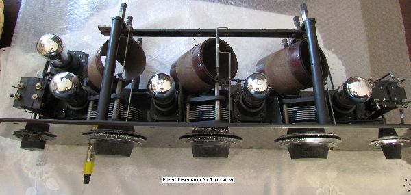
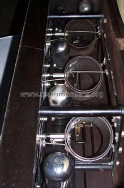
Top View während der Ausprobe.

Attachments
- Schaltplan (110 KB)
- USA_Freed_eisemann_nr.5_tested (82 KB)
Friedrich Weber † 12.09.2014, 14.Sep.13
Dear Friends,
After the compliance status: 2 tubes, 2 audio transformers and the battery setup adjustment are broken.I tried to compare the real wiring with the schematic which is uploaded here. But the schematic is in a poor quality, the connection points cannot be defined surely. More and more I discover the wiring, the differencies would be bigger. In the case I had recover the whole schematic by myself. So a lot of surprises came up, e.g. no grid battery is included, the terminals C- and C+ are missing. One heating adjustment - can be called battery setup - are connected to all tubes exception of tube 3 -detector place-, the second heating adjsutment controls the heating of tube 3, only. What is the truth?
Nevertheless, that's how the model originally looked like. The soldering points looks old and the wiring was done in with square profil wires. The No.5 looks really untouched.
But how can the work go further with it? May the comparision with an other No.5 will given the real good basic to recover the original schematic diagram.
I asked John Kusching, whom I know from cooperation from RMorg, for help. We sent us detail photos from both No.5 and we realized that both No 5 ware exactly the same. From John I got a schematic diagramm in good quality and I put all registered changes in it. Also the technical data and the names of the components were updated.
In our teamwork the big surprise was that we found out, the No. 5 works without grid battery.After completion, John reviewed his radio again ad drew a new schematic diagram with all details.
For me the engagement is exemplary. My work was crowned with success and in the RMorg now a valid schematic is available. John has also updated the description of the RMorg model.
Although there is huge distance from USA to germany.
Thank you John for help. A complete report about the restore history will come up.
Attachments
- Freed Eisemann No.5 (110 KB)
Friedrich Weber † 12.09.2014, 26.Jul.13
.png) Hallo Radiofreunde,
Hallo Radiofreunde,
versuche einen Freed Eisemann Nr.5 zu restaurieren. Zum Verständnis prüfe ich immer erst den Plan, ob das auf dem Tisch stehende auch das richtige Modell ist. Der Schaltplan zeigt Anschlüsse bezeichnet mit -C und +C. Das Gerät arbeitet normal mit +90V DC Anode 1 und +45V Anode 2 und 6V Heizung.
Der Plan ist leider zu unscharf, sodass man einzelne Verbindungspunkte raten muss. Das macht die Planprüfung zum Lotteriespiel. Ich rate, C, das müßte ans Chassis und sollte irgendwo an -6 oder -C. Hat jemand einen besseren Plan? oder was könnte +C und -C bedeuten. Laut Rückwandplan mit den Batterieanschlüssen gibt es kein C?
Vielen Dank für eine Information
Friedrich Weber † 12.09.2014, 05.Jul.13
I have a Freed Eismann NR-5 that does not play. I checked the grid-leak cap and it showed up at 120K. Is this correct? The resistor checks at a steady 2 meg.
Thanks.
Please post only from the model side. I scrolled your thread to the model.
Wolfgang Bauer
Wyatt CIRCO, 09.Aug.09

