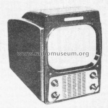
800 (800C, 800D) "Locomotive" late
General Electric Co. (GE); Bridgeport CT, Syracuse NY
- Land
- USA
- Hersteller / Marke
- General Electric Co. (GE); Bridgeport CT, Syracuse NY
- Jahr
- 1949
- Kategorie
- Fernseh-Empfänger/Monitor
- Radiomuseum.org ID
- 170091
-
- Marke: Musaphonic
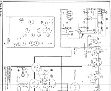
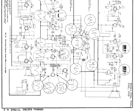
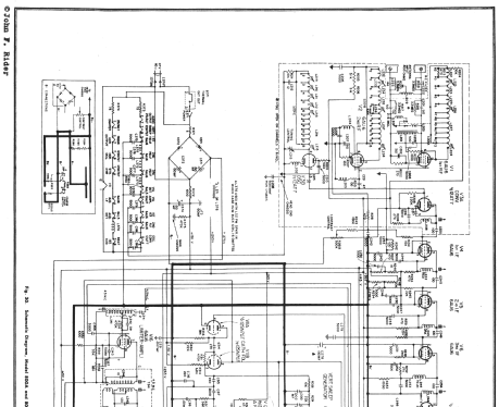
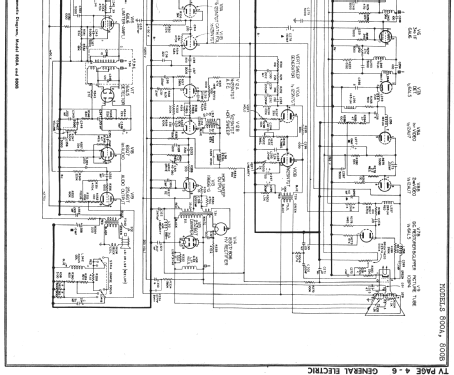
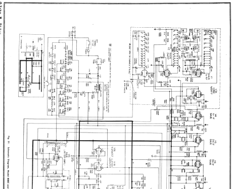
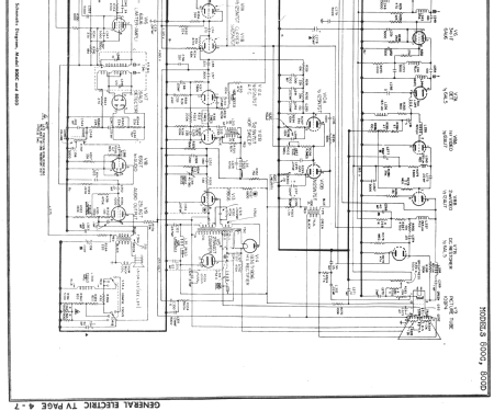
Klicken Sie auf den Schaltplanausschnitt, um diesen kostenlos als Dokument anzufordern.
- Anzahl Röhren
- 19
- Röhren
- 6AU6 6AU6 12AT7 6AU6 6AU6 6AU6 6AL5 12AU7 10BP4 12SN7GT 12SN7GT 12SN7GT 19BG6G 1B3GT 25W4GT 6AU6 6AL5 6SQ7 25L6GT
- Hauptprinzip
- Super mit HF-Vorstufe; ZF/IF 26300/4500 kHz
- Wellenbereiche
- Wellen in den Bemerkungen.
- Betriebsart / Volt
- Wechselstromspeisung / 115 Volt
- Lautsprecher
- Dynamischer LS, Prinzip (Edyn oder Pdyn) nicht gegeben. / Ø 4 inch = 10.2 cm
- Belastbarkeit / Leistung
- 1 W (Qualität unbekannt)
- Material
- Bakelit (Pressstoff)
- von Radiomuseum.org
- Modell: 800 "Locomotive" [late] - General Electric Co. GE;
- Form
- Tischmodell, Zusatz nicht bekannt - allgemein.
- Abmessungen (BHT)
- 11.4 x 15 x 21 inch / 290 x 381 x 533 mm
- Bemerkung
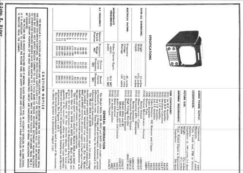
- In 1949-50, General Electric produced multiple models of 10-inch TVs with an upright bakelite cabinet with a streamlined appearance. These models are very popular with antique TV collectors today and have have been given the nickname "Locomotive" because of their unique shape (and possibly because GE also produces actual train locomotives). All sets in this series have 12-channel VHF tuners and use intercarrier sound. Some early models have electromagnet-type speakers; later models have PM speakers.
The earliest models in the series are the 800A, 800B, and 805 early version (with no letter chassis marking). Rider states that the difference between the 800A and 800B relates to the lengths of the front panel control shafts. All models in this grouping have a rectangular CRT mask. Electrically, all three models appear to be identical, with 19 tubes (including 25Z6GT damper tube, unique to these models), and a full-wave voltage doubler which provides a "split" or "stacked" B+ arrangement. These early models have a focus coil that can be adjusted to slide forward or backwards, but not twist; picture centering is accomplished with a separate centering ring on the neck of the CRT. The difference between the 800 and 805 models is not clear, nor is the chronological order of production of these three models clear.
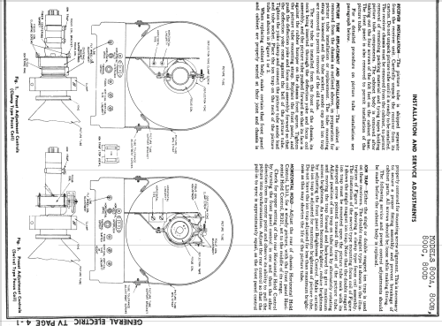
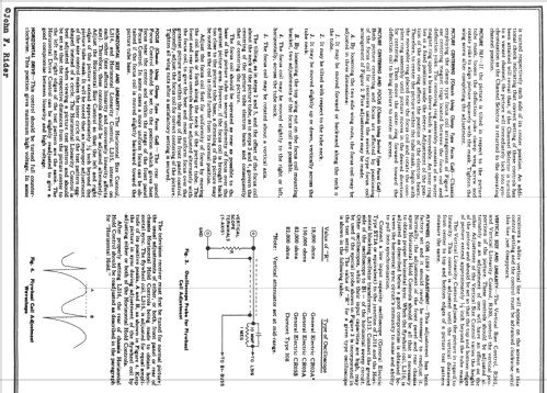
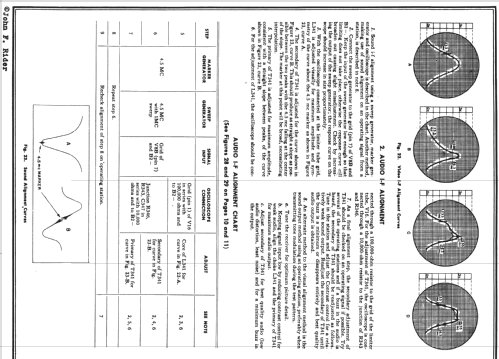
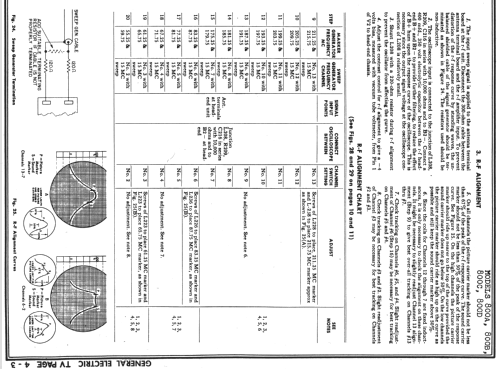
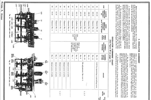
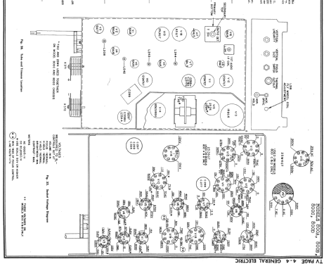
Based on examination of the circuitry shown in Rider, it can be concluded that the next grouping of models produced includes the 800C, 800D, and the middle versions of the 805 (with S or T chassis). Like the first grouping, these models have rectangular CRT mask. These models have 19 tubes including a 25W4GT damper, and a half-wave voltage doubler is used in a slightly modified stacked B+ arrangement. There are minor differences visible on the schematics between the 800 and 805 models in this grouping, and Rider notes a control shaft length diffrence between 800C and 800D. Additional degrees of freedom are provided for the adjustment of the focus coil, allowing the centering to be adjusted by sliding/rotation of the focus coil, and eliminating the need for a separate centering ring. The chronological ordering of models within this grouping is not clear.
Next came the late versions of the 805 (with U and W chassis). In this model, GE added an additional tube (20 tubes total) for an improved horizontal synchronization circuit. A 6AL5 dual diode was used for the horizontal discriminator, and a 12SN7GT used in the sync separator circuitry was replaced with a 6SL7GT (thus allowing the series filamant strings to have minimal change from previous models). Another change is the use of a 6AG5 tube in place of a 6AU6 in the tuner second RF stage. Although Rider and most advertising literature shows rectangular CRT mask for all 805 models, there is some possibility that some of the late 805s had a double-D mask.
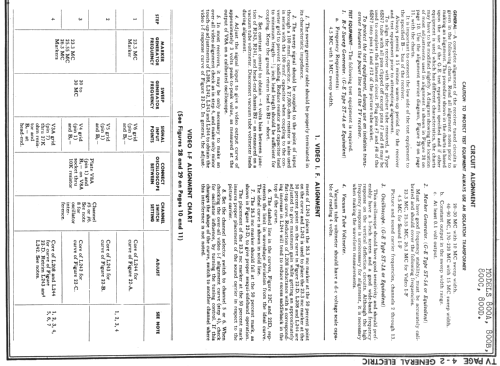
The 805 was replaced by the 10T1, in which another tube was added (2nd 6AU6 sound IF) and one was removed (6AL5 video det / DC restorer replaced by germanium diodes). In the video IF stages, type 6AG5 replaced the earlier 6AU6 tubes. According to Rider, starting in January 1950, these 6AG5s in the video IF, and the 6AG5 in the tuner second RF stage were all replaced with 6BC5. This establishes a date of January 1950 for some point during the 10T1 model run. The 10T1 has a double-D CRT mask.
The last model in the series is the 10T6, which includes all of the changes noted above, and uses a 10FP4A CRT with aluminized screen in place of the earlier 10BP4 for brighter picture and elimination of the need for an ion trap. Since January 1950 occured during 10T1 production, it is assumed that the 10T6 is a 1950 model.
Collectors should note that due to fragility of the bakelite cabinet, it is wise to ship the chassis, CRT, and cabinet separately. These models were originally shipped by GE with CRT not installed.
- Schaltungsnachweis
- Photofact Folder, Howard W. SAMS
- Literatur/Schema (1)
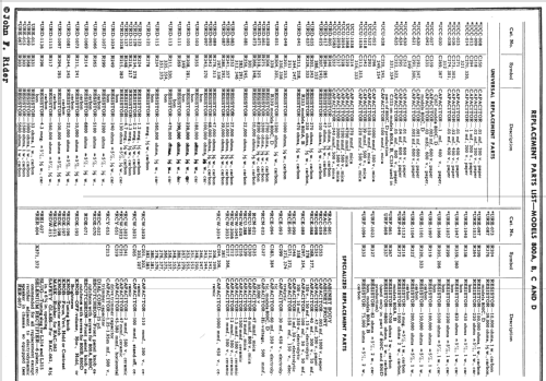
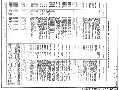
- Rider TV 4-1; SAMS set 78 folder 7
- Autor
- Modellseite von Thomas Albrecht angelegt. Siehe bei "Änderungsvorschlag" für weitere Mitarbeit.
- Weitere Modelle
-
Hier finden Sie 2920 Modelle, davon 2143 mit Bildern und 2046 mit Schaltbildern.
Alle gelisteten Radios usw. von General Electric Co. (GE); Bridgeport CT, Syracuse NY
