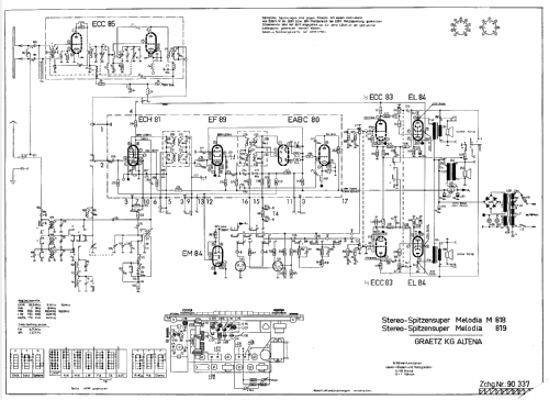
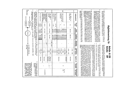
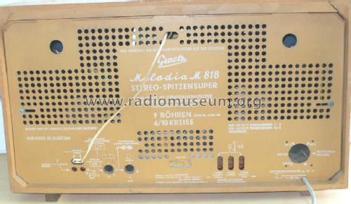
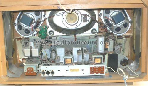
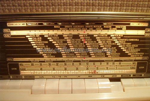
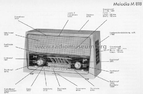
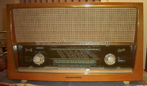
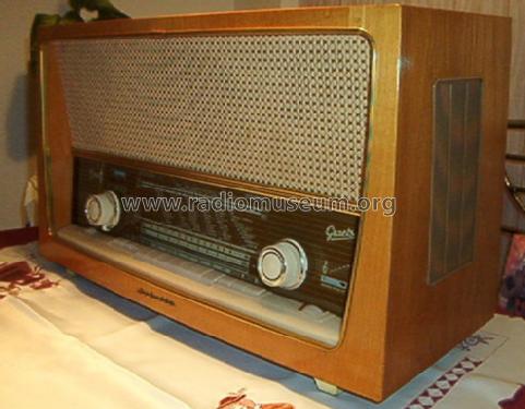
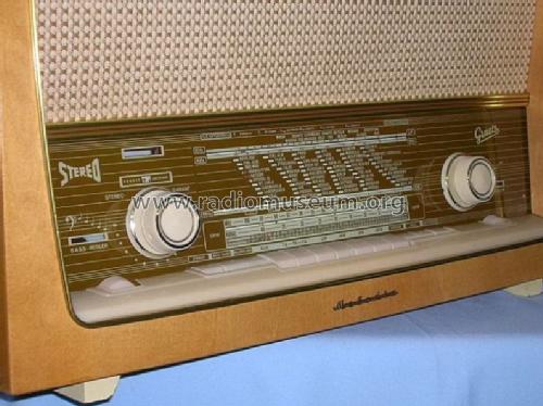
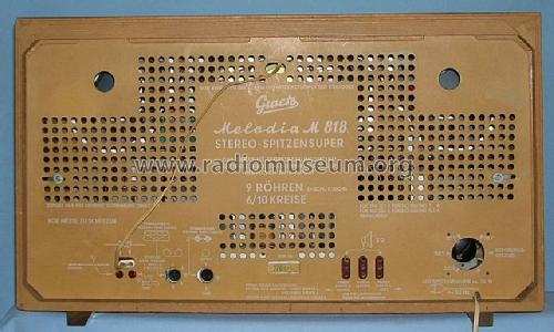
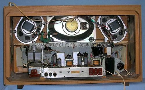
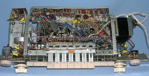
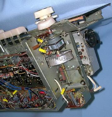
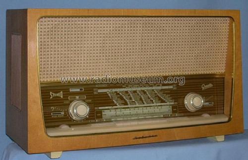
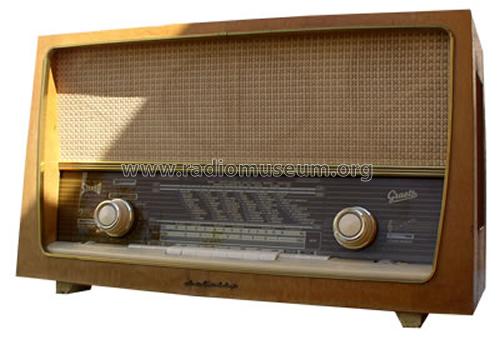
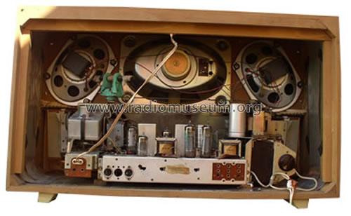
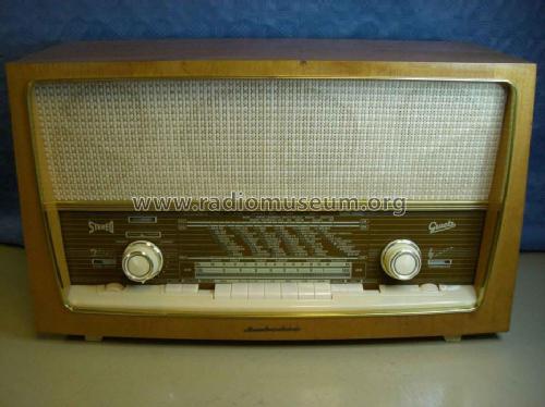
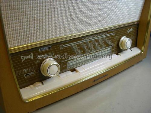
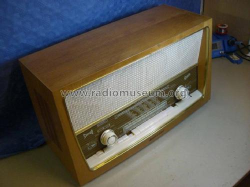
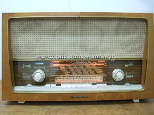
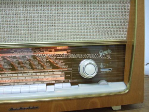
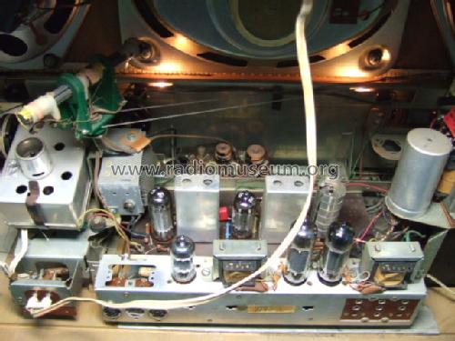
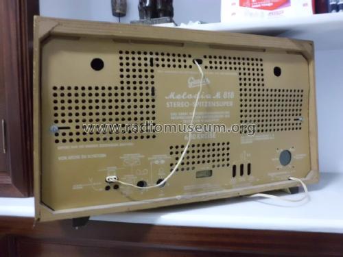
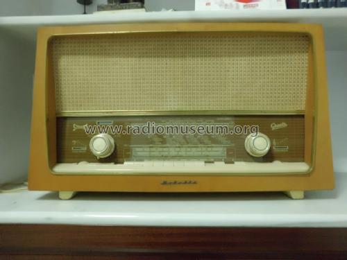
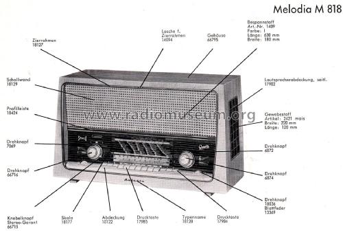
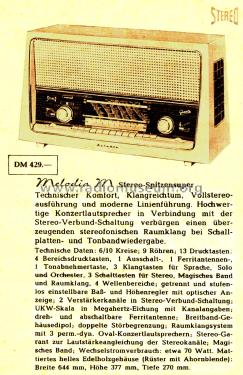
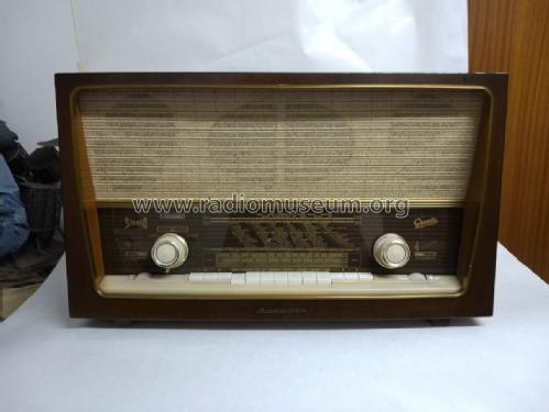
Melodia M818
Graetz, Altena (Westfalen)
- País
- Alemania
- Fabricante / Marca
- Graetz, Altena (Westfalen)
- Año
- 1959/1960
- Categoría
- Radio - o Sintonizador pasado WW2
- Radiomuseum.org ID
- 22081
Haga clic en la miniatura esquemática para solicitarlo como documento gratuito.
- Numero de valvulas
- 8
- Numero de transistores
- Semiconductores
- B250C125
- Principio principal
- Superheterodino en general; ZF/IF 460 / 6750 kHz; 2 Etapas de AF
- Número de circuitos sintonía
- 6 Circuíto(s) AM 10 Circuíto(s) FM
- Gama de ondas
- OM, OL, OC y FM
- Tensión de funcionamiento
- Red: Corriente alterna (CA, Inglés = AC) / 110; 127; 150; 220 Volt
- Altavoz
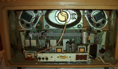
- 3 Altavoces
- Potencia de salida
- 9 W (unknown quality)
- Material
- Madera
- de Radiomuseum.org
- Modelo: Melodia M818 - Graetz, Altena Westfalen
- Forma
- Sobremesa de botonera.
- Ancho, altura, profundidad
- 645 x 375 x 270 mm / 25.4 x 14.8 x 10.6 inch
- Anotaciones
- Ferritantenne dreh - und schaltbar.
- Peso neto
- 13 kg / 28 lb 10.1 oz (28.634 lb)
- Precio durante el primer año
- 429.00 DM
- Ext. procedencia de los datos
- Erb
- Procedencia de los datos
- HdB d.Rdf-& Ferns-GrH 1959/60
- Mencionado en
- - - Manufacturers Literature (Katalog 1959/60)
- Documentación / Esquemas (1)
- -- Original-techn. papers. (Service-Manual)
- Otros modelos
-
Donde encontrará 779 modelos, 700 con imágenes y 596 con esquemas.
Ir al listado general de Graetz, Altena (Westfalen)
Colecciones
El modelo Melodia es parte de las colecciones de los siguientes miembros.
Contribuciones en el Foro acerca de este modelo: Graetz, Altena: Melodia M818
Hilos: 1 | Mensajes: 3
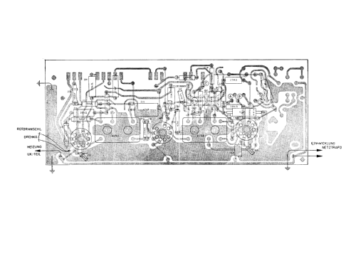
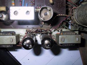
Bei meinem Grätz Melodia M 818 sind hinter den beiden Endstufenröhren zwei Widerstände montiert, die im Schaltplan nicht eingezeichnet sind. (Bild 1)
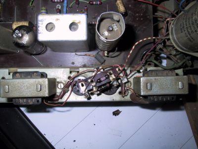
Die Widerstände sind leider verkohlt und die Werte lassen sich nicht mehr ablesen (Bild 2; Röhren entfernt):
Wer kann mir sagen welche Werte hier nötig sind und warum diese beiden Widerstände (ich denke sie begrenzen evtl. den Anodenstrom) nicht im Plan eingezeichnet sind und evtl. nachträglich in die Produktion mit aufgenommen wurden ?

Die Widerstände sind leider verkohlt und die Werte lassen sich nicht mehr ablesen (Bild 2; Röhren entfernt):

Wer kann mir sagen welche Werte hier nötig sind und warum diese beiden Widerstände (ich denke sie begrenzen evtl. den Anodenstrom) nicht im Plan eingezeichnet sind und evtl. nachträglich in die Produktion mit aufgenommen wurden ?
Reinhard Ziegler, 26.Oct.04
