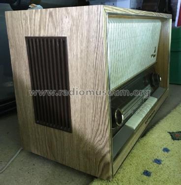
Konzertgerät 4295 Stereo Nussbaum
Grundig (Radio-Vertrieb, RVF, Radiowerke); Fürth/Bayern
- Country
- Germany
- Manufacturer / Brand
- Grundig (Radio-Vertrieb, RVF, Radiowerke); Fürth/Bayern
- Year
- 1961/1962
- Category
- Broadcast Receiver - or past WW2 Tuner
- Radiomuseum.org ID
- 23778
-
- alternative name: Grundig Portugal || Grundig USA / Lextronix
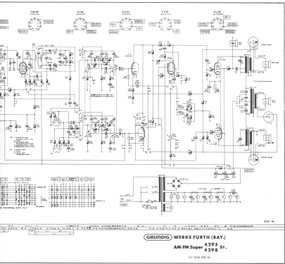
Click on the schematic thumbnail to request the schematic as a free document.
- Number of Tubes
- 7
- Main principle
- Superheterodyne (common); ZF/IF 460/10700 kHz
- Tuned circuits
- 6 AM circuit(s) 12 FM circuit(s)
- Wave bands
- Broadcast, Long Wave, Short Wave plus FM or UHF.
- Power type and voltage
- Alternating Current supply (AC) / 110; 125; 220 Volt
- Loudspeaker
- 4 Loudspeakers
- Power out
- 5 W (unknown quality)
- Material
- Wooden case
- from Radiomuseum.org
- Model: Konzertgerät 4295 Stereo [Nussbaum] - Grundig Radio-Vertrieb, RVF,
- Shape
- Tablemodel with Push Buttons.
- Dimensions (WHD)
- 625 x 360 x 270 mm / 24.6 x 14.2 x 10.6 inch
- Notes
- Dioden: 2× OA172, BA102. Stereo-NF-Verstärker, 5-W-Gegentakt-Enstufe in Zweiwegetechnik.
- Net weight (2.2 lb = 1 kg)
- 12 kg / 26 lb 6.9 oz (26.432 lb)
- Price in first year of sale
- 467.00 DM
- External source of data
- Erb
- Source of data
- HdB d.Rdf-& Ferns-GrH 1961/62
- Other Models
-
Here you find 6214 models, 5447 with images and 4211 with schematics for wireless sets etc. In French: TSF for Télégraphie sans fil.
All listed radios etc. from Grundig (Radio-Vertrieb, RVF, Radiowerke); Fürth/Bayern
Forum contributions about this model: Grundig Radio-: Konzertgerät 4295 Stereo
Threads: 2 | Posts: 4
Kai Albers asked in a German language post about the stereo operation of the two tube audio amplifier in this radio.
Hello Kai,
You seem just as fascinated about this unusual 3 channel stereo circuit, as I was when I first saw it in a Motorola phonograph amplifier. One example is the Motorola SP27.
There are two aspects of the operation that make this type of amplifier different from more conventional designs.
2 pentodes drive 3 channels
The two output pentodes drive three speakers/channels, with one speaker as woofer, and the other 2 as L and R side speakers. You are correct in drawing a similarity to modern systems with a single woofer and separate small side speakers. There is no directional content at bass frequencies, so there is no need for more than one speaker.
The bass frequencies usually carry the most power, and set the size of the iron core in the ouput transformer. But low distortion is important at the woofer, because it's position could be identified by the harmonic content. See this thread for more detail about center channel woofer distortion.
The larger transformer between the pentode plates is driven in a familiar push-pull arrangement, but with a filter capacitor in parallel with the primary, to short out the higher frequency content. The push-pull configuration greatly reduces the size of the bass output transformer because there is no net DC current to saturate the core.
At higher frequencies, the primary of the push-pull transformer shorts out progressively, while the much smaller and lower inductance single ended L and R transformers start to carry more of the L and R signal. The cross-over action helps share plate headroom between the center bass channel and the L and R channels.
Note that these two side transformers have a reduced inductance value that serves as cross-over in combination with the capacitor accross the bass center channel transformer, which has much higher inductance.
The reduced inductance of the side transformers, means that they can be smaller for the same saturation performance.
This is a very efficient allocation of transformer costs. Motorola, used this 3-channel scheme in many models in the early 1960's, ranging from portable phonographs to top-of-the-line consoles. Grundig used this scheme in a few models.
Phase inversion
The other aspect of this scheme is how the phase inversion is done to drive the center Bass channel in push-pull.
In the simplest 3 channel phonograph amplifiers from Motorola, such as the Motorola SP27, there is no separate phase inverter/splitter stage. The phase inversion is done right at the ceramic phono cartridge, simply by reversing one of the two channel wires. You can see this if you look closely at the phono cartridge connection in the schematic.
--------------------
In the case of the Grundig 4295, the phase inverter is the triode in the EM84
The phase inverter topology for the EM84 is the kind that looks like an inverting operational amplifier with a feedback resistor Rf and an input resistor Ri. The values of Rf and Ri would ideally be equal, but it is likely that RF is a little larger than Ri to make up for gain losses and finite tube gain, and achieve a net fed back gain of -1.
The schematic is a blurry, but I have identified the inverting resistor pair for the EM84 triode as the two resistors in the schematic that sit horizontally directly above the EM84, and are AC-coupled to the grid.
The upper ECC83 triode always works as audio preamp for mono, or Left channel in stereo.
The lower ECC83 works as a matched audio preamp in stereo for the Right channel. In radio operation, the reception is mono and this audio preamp for the right channel is no longer needed, so it is switched for operation as the triode driver to the EM84 for radio tuning indication.
The schematic is not clear, but mono operation from an external source should simply short the channels together, while keeping the amplifer wired as if in stereo mode.
The presumption here is that the all Stereo music content comes from an external source, such as a tape player or phonograph. This radio has no socket for an external FM Multiplex decoder. The EM84 phosphor target is turned off in stereo mode.
In stereo mode, the ECC83 works as a pair of matched preamplifiers, while the triode in the EM84 is always the phase inverter, as it was in mono.
When listening to the Radio, the reception is mono, so there is no longer a need for a matched stereo preamp. Now the lower half of the ECC83 triode is freed up for tuning indication, while the upper half of the ECC83 works as preamp and the EM84 is always the phase inverter.
Always using the triode in the EM84 as phase inverter, means that the ECC83 can be used as a matched pair for the stereo preamp.
Regards,
-Joe
Joe Sousa, 18.Dec.09
Liebe Radiofreunde,
bei Ebay habe ich einen 4295 Stereo gesehen, darum hab ich mir den bei uns angesehen.
In der Beschreibung steht "5W Gegentaktendstufe in Zweiwegetechnik"
Im Schaltplan sehe ich aber zwei NF-Verstärkerzüge, die dann über zwei Ausgangsübertrager auf einen gemeinsamen Ausgangsübertrager wirken. Eine Phasenumkehrstufe sehe ich nicht.
Ich blicke nicht wirklich durch bei dieser Schaltung, aber eine Gegentaktendstufe ist das doch wohl nicht? Dann müsste die Beschreibung aber geändert werden. Wenn ich das richtig verstehe, was ich da ich Schaltplan sehe, dann lässt der gemeinsame Übertrager nur die tiefen Frequenzen durch. Das setzt allerdings voraus das der Übetrager gleichsinnig gewickelt ist? Ein frühes 2.1 System, könnte man sagen? Wirklich eine interessante Schaltung.
Vielleicht kann jemand der mehr als ich davon versteht das mal prüfen und eventuell richtig stellen.
Herzliche Grüße, Kai Albers
Kai Uwe Albers, 17.Dec.09


