Stereo-Decoder (1)
Grundig (Radio-Vertrieb, RVF, Radiowerke); Fürth/Bayern
- Hersteller / Marke
- Grundig (Radio-Vertrieb, RVF, Radiowerke); Fürth/Bayern
- Jahr
- 1962 ?
- Kategorie
- Radio Baugruppe nach 1925 (kein Bauteil, keine Taste)
- Radiomuseum.org ID
- 131450
-
- anderer Name: Grundig Portugal || Grundig USA / Lextronix
Klicken Sie auf den Schaltplanausschnitt, um diesen kostenlos als Dokument anzufordern.
- Anzahl Röhren
- 1
- Röhren
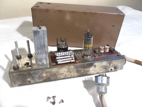
- 6BH6
- Anzahl Transistoren
- Halbleiter
- OA90
- Wellenbereiche
- - ohne
- Betriebsart / Volt
- Externes Speisegerät / Netzgerät / Hauptgerät
- Lautsprecher
- - Für Kopfhörer oder NF-Verstärker
- Material
- Metallausführung
Die GFGF Zeitschrift Funkgeschichte bringt interessante Artikel zu Radios, Funkwesen und Medien. Bei Radiomuseum.org finden Sie die vollständigen Hefte früherer Ausgaben als PDF zum Download.
- von Radiomuseum.org
- Modell: Stereo-Decoder - Grundig Radio-Vertrieb, RVF,
- Form
- Chassis - Einbaugerät
- Bemerkung
-
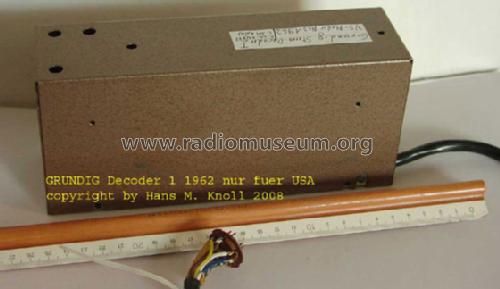
Dioden: 6× OA90 - Dieser Decoder wurde für die USA Geräte nach FCC Norm entwickelt.
Wurde beispielsweise im Grundig Steuergerät 3299 U/S/ Stereo verwendet.
- Literatur/Schema (1)
- -- Original-techn. papers.
- Literatur/Schema (2)
- Funkschau (5/1962, S. 115 f.)
- Autor
- Modellseite von Heribert Jung angelegt. Siehe bei "Änderungsvorschlag" für weitere Mitarbeit.
- Weitere Modelle
-
Hier finden Sie 6251 Modelle, davon 5496 mit Bildern und 4255 mit Schaltbildern.
Alle gelisteten Radios usw. von Grundig (Radio-Vertrieb, RVF, Radiowerke); Fürth/Bayern
Sammlungen
Das Modell Stereo-Decoder (1) befindet sich in den Sammlungen folgender Mitglieder.
Forumsbeiträge zum Modell: Grundig Radio-: Stereo-Decoder
Threads: 2 | Posts: 6
Liebe Leser,
als ich vor einigen Monaten beim Stöbern nach dem Schaltbild eines bestimmten amerikanischen Stereodecoders diese Grundig-Schaltung zum ersten Mal sah, war ich zunächst etwas ratlos. Was sollte das denn bloß sein ? Ein Oszillator oder sonst irgendein rückgekoppeltes schwingfähiges Gebilde ? Es war aber unter der Überschrift "Stereo-Decoder" abgelegt. Bei genauerem Hinsehen und Nachdenken kommt man allmählich dahinter, faszinierend, und, wie ich erst kürzlich bemerkte, schon vor etwa einem Jahr hatte uns Herr Sousa freundlicherweise die ausführliche Erklärung im Radiomuseum zur Verfügung gestellt. Um auch unsere deutschsprachigen Leser mit einzubeziehen, bin ich seinem Vorschlag gefolgt und habe die Übersetzung angefertigt. Vielen Dank an Herrn Knoll für das Korrekturlesen.
Ein Hinweis: Den englischen Originaltext von Herrn Joe Sousa finden Sie hier.
Grundig stellte verschiedene UKW-Stereo-Decoder für den US-amerikanischen Markt her. Die hier behandelte Ausführung benötigt nur eine einzige Röhre zur vollständigen Stereo-Decodierung durch die Anwendung der Reflex-Technik.
Reflexschaltungen wurden in den 1920er Jahren erstmals angewendet, um dieselbe Röhre zur HF-Verstärkung vor dem Detektor und zur Verstärkung des NF-Signals nach dem Detektor verwenden zu können. Der damals mit diesem Verfahren verfolgte Zweck war die Kostenersparnis.
Der Grund für die Anwendung von Reflexschaltungen in diesem Decoder und in Grundigs Reihe von Dreiröhren-UKW/MW-Tischradios von der Mitte der 50er bis zur Mitte der 60er Jahre war die Einsparung bei der Röhrenanzahl für den deutschen Markt, wo die Radiogeräte nach der Anzahl ihrer Röhren besteuert wurden.
Als Beispiele für die Anwendung von Reflex-Eingangsschaltungen seien hier einige Tischradios von Grundig mit den Modell-Nummern 80U, 85, 87, 88, 92, 101U und 2550 genannt.
In jeder Reflexschaltung verstärkt dieselbe Röhre Signale in unterschiedlichen Frequenz-bereichen, ohne dass es zu einer gegenseitigen Beeinflussung der Signale kommt.
Bei dieser Schaltung wird ein Stereo-Multiplex-Signal von bis zu mehreren Volt Amplitude an den Eingang IV gelegt. Dieses Signal stammt von einem breitbandigen FM-Demodulator, der das (R–L) Seitenbandsignal im Bereich von 15 kHz unter 38 kHz bis 15 kHz über 38 kHz (also 23 bis 53 kHz) ebenso verarbeiten kann wie den mit 10% Tiefe modulierten sinusförmigen19 kHz Pilotton.
Der niederfrequente Signalanteil von 20 Hz bis 15 kHz, das Monosignal, wird von allen (auch den nicht-stereophonen) UKW/FM-Empfängern wiedergegeben.
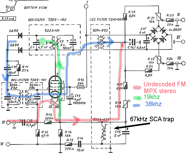
Das Kathodenpotenzial an Pin 2 der Pentode 6BH6 folgt einfach dem beschriebenen undecodierten Eingangssignal ("Kathodenfolger") und steht an R14 mit niedriger Impedanz zur Weiterleitung mit R18 bis R22 zur Verfügung und treibt die Brückenschaltung mit den vier Schaltdioden OA90 (Signalweg im Schaltbild rot markiert).
C15 = 2nF und die zugehörige Induktivität 9204-051 bilden einen Filter zur Löschung eines etwa vorhanden 67 kHz Signals des SCA-Dienstes (Subscription CArrier). Dieses Signal hat nichts mit der Stereo-Decodierung zu tun, es enthält eine Mono-Hintergrundmusik für Geschäftsräume, Restaurants und Fahrstühle auf Abonnement-Basis.
Ich habe das Stereo-Multiplex-Signal als eine Reihe von Frequenzbereichen beschrieben. Aber wenn man dieses Signal mit dem Oszilloskop ansieht, wird man feststellen, dass sich diese Komponenten aus mehreren Frequenzbereichen mischen mit dem Ergebnis eines 38 kHz-Hüllkurvensignals, in dem der linke Kanal in den ungeraden Halbwellen und der rechte Kanal in den geraden Halbwellen enthalten ist.
Das bedeutet, dass ein einfaches Verfahren zur Trennung der L und R Signale darin besteht, das undecodierte Signal für die Dauer der ungeraden Halbwelle mit dem linken Kanal und während der Dauer der geraden Halbwelle der modulierten 38 kHz-Schwingung mit dem rechten Kanal zu verbinden.
Ein Mono-Signal hat gleich große L und R Amplituden, daher ist keine Differenz L-R von ungeraden Halbwellen zu geraden Halbwellen bei einer Frequenz von 38 KHz zu erkennen. Das gilt auch für den Fall der FM-Stereo-Rundfunk-Übertragung einer alten Mono-Schallplatte.
Die OA90-Diodenbrücke schaltet immer dann, wenn ihre Dioden von dem 38-kHz-Signal konstanter Amplitude in den leitenden oder gesperrt Zustand gesteuert werden, das von dem auf 38 kHz abgestimmten Transformator 9204-53 stammt, dessen Sekundärseite den linken und den rechten Eingang der OA90-Brücke betreibt.
Das Schalten der Brücke kann auf mehrere Arten bewerkstelligt werden.
In dieser Schaltung mit dem die Brücke treibenden 38 kHz Transformator wird eine konstante hohe (38 kHz-) Amplitude zum Eingangssignal aus dem Kathodenfolger addiert, so dass dessen ungerade 38 kHz-Halbwellen sehr viel mehr positiv werden als die geraden negativen Halbwellen.
Das Endergebnis an C17 sieht wie ein amplitudenmoduliertes Signal mit 38 kHz Trägerfrequenz aus mit dem linken Kanal als eingeprägte positive Hüllkurve und dem rechten Kanal als eingeprägte negative Hüllkurve.
Dies erklärt, warum die Kathoden der OA90-Brücke der positiven Hüllkurve folgen und den Ausgang II treiben, während die Anoden der OA90 der negativen Hüllkurve folgen und den Ausgang I treiben.
Aus dem Schaltbild geht nicht hervor, welcher der beiden Ausgänge I und II der rechte oder der linke Kanal ist.
Möglicherweise habe ich die Zuordnung rechts und links vertauscht, aber das ist für die Erklärung nicht wichtig.
Durch dieses spezielle Verfahren der Abtastung der positiven und der negativen Hüllkurve werden positive und negative Gleichspannungsanteile an den Ausgängen Kanal I und II erzeugt. Diese werden durch Koppelkondensatoren blockiert, die sich ausserhalb dieser Schaltung befinden. Der (zugehörige) externe Stereo-Verstärker enthält ausserdem ein C-L-C Pi-Filter, das Frequenzen oberhalb von 15 kHz abschneidet.
Bis hierher wurde kein Reflexverfahren angewendet. Tatsächlich kann man die notwendige konstante 38 kHz Hilfsträgerfrequenz zum Umschalten der Brücke aus dem (Multiplex-) Eingangssignal mit einer Reihe weiterer Röhrenstufen gewinnen, wie es bei weniger eleganten Stereo-Decodern üblich ist.
Bei Anwendung des Reflexverfahrens muss der 19 kHz Pilotton, der nur etwa 10% des Eingangssignals ausmacht, mit einem Filter abgetrennt, verstärkt und in der Frequenz verdoppelt werden, um daraus das erforderliche 38 kHz-Hilfsträgersignal mit konstanter Amplitude zu erzeugen. Dieser mit dem MPX-Eingangssignal (und damit auch mit dem Sendersignal !) synchrone Hilfsträger wird von der OA90-Brücke zur Abtrennung des L- und des R-Signals zu den entsprechenden Ausgängen benötigt, wie oben beschrieben.
Die Reihenschaltung R15 mit C14 und C15 wirkt als niedrige Impedanz für hohe Frequenzen und überbrückt den Kathodenwiderstand R 14 an der Kathode Pin 2 der 6BH6 Pentode nach Masse, so dass der 19 kHz-Pilotton, der am an Gitter 1 anliegt, hoch verstärkt wird und an der Anode zur Verfügung steht. Das Schaltbild zeigt den 19kHz-Pfad in grüner Farbe.
Das Anodensignal speist einen auf 19 kHz abgestimmten zweikreisigen Transformator 9223-101 mit 6 parallelen Kondensatoren je 180 pF auf der Primär- und 4,7 nF auf der Sekundärseite. Das hoch übersetzte 19 kHz Signal speist zwei Dioden OA 90.
Die anschließende Zweiweg-Gleichrichtung mit den Dioden bewirkt eine Frequenzverdopplung des sinusförmigen Pilottons von 19 kHz auf 38 kHz.
Mit dem nachfolgenden auf 38 kHz abgestimmten zweikreisigen Filter 7209-102 mit C2 = 3.5nF auf der Primär- und C1 = 1.5nF auf der Sekundärseite wird aus dem gleichgerichteten 19 kHz Signal eine saubere Sinusschwingung von 38 kHz erzeugt. Die Sekundärseite des 38 kHz-Filters liegt in Serie mit dem Eingangssignal am Steuergitter 1 der Pentode.
Jetzt erkennen wir, dass am Steuergitter sowohl das ursprüngliche undecodierte Signal als auch das daraus erzeugte neue 38 kHz-Signal mit konstanter Amplitude anliegen.
Damit tritt auch das 38kHz Hilfsträger-Sinussignal verstärkt an der Anode Pin 5 auf, wird mit dem einkreisigen, auf 38 kHz abgestimmten Transformator 9204-53 vom Anodenstrom abgetrennt und treibt die OA90-Gleichrichterbrücke (Das Signal ist im Schaltbild blau markiert).
Insgesamt führt die 6BH6 drei getrennte Verstärkungsvorgänge durch: Sie puffert das Multiplex-Eingangssignal an ihrer Kathode, verstärkt das niedrig pegelige 19 kHz-Pilotsignal zur Frequenzverdopplung, und sie verstärkt die 38 kHz-Hilfsträgerspannung zum Schalten der OA90-Diodenbrücke.
Eine Reflexschaltung mit einer einzigen Röhre, die drei verschiedene Signale (verstärkt bzw.) verarbeitet, könnte einen Rekord bezüglich der Anzahl von Operationen darstellen. Die üblicherweise in Reflexschaltungen verstärkte Anzahl von Signalen beträgt (nur) zwei.
-------------------------------------------------
Deutsche Übersetzung von Rolf Nickel, Lektorat Hans M. Knoll, für www radiomuseum.org 2009-05-30
Ed. 30.05.2009: Schreibfehler und Titel korrigiert
Ed. 12.03.2018: "toter" Link nach extern entfernt, int. Links zu Modellen ergänzt
Rolf Nickel, 30.May.09
Grundig made several FM stereo Multiplex (MPX) decoders for the USA market. This model makes use of a single Pentode to accomplish full stereo decoding using REFLEX techniques. Reflex techniques were pioneered in the 1920's as method to use the same tube to amplify RF signals before detection, and AF signals after detection. The motivation in the 1920's was to save cost.

Grundig's motivation to use Reflex circuits in this stereo decoder, and in their line of 3-tube AM-FM table radios from the mid 50's to the mid 60's, was also to save on tube count for the German market, where radios were taxed by the number of tubes. For examples of Reflex FM front end circuits see 3 tube table radio Grundig models 85,87,88,92,101.
In every Reflex circuit the tube amplifies signals in different frequency bands without interference among the signals.
In this circuit, an undecoded FM stereo Multiplex signal up to several volts in amplitude is applied to input IV. This signal comes from a wide band FM detector that can pass the R-L sideband signals ranging from 15kHz below 38kHz, to 15kHz above 38kHz, as well as the 19kHz 10% modulation pilot sinewave. Low frequency signals from 20Hz to 15kHz carry the L+R mono signal that all FM radios reproduce.
The cathode at pin2 of the 6BH6 Pentode simply follows the undecoded signal just described and presents a low impedance to R18-R22,which, in turn, drive the OA90 diode switching/decoding bridge.
C15=2nF and the associated inductor provide a filter to kill the 67kHz signal that may be present for the SCA (Subscription CArrier) music service. This signal has nothing to do with stereo decoding; it provides mono background music by subscription to businesses, restaurants and elevators.
I described the FM stereo Multiplex signal as a series of frequency components. But if you look at this signal on an oscilloscope, you can see that these various frequency components combine to produce a signal envelope that has the Left channel represented in the odd half cycles of 38kHz, while the Right channel is represented on in the even half cycles of 38kHz. This means that one simple method to separate the L and R signals is to connect the undecoded signal to the Left channel when the 38kHz wave is in the odd cycle, and to the Right channel when the modulated 38kHz wave is in the even half cycle.
A mono signal has equal L and R amplitudes, so you see no L-R difference from odd half cycles to even half cycles at a 38kHz rate. This is also true with an FM stereo transmission that is broadcasting an old mono record.
The OA90 diode bridge accomplishes the switching action when it's diodes are turned on and off by the fixed amplitude 38kHz signal coming from 38kHz tuned transformer driving the left and right ends of the OA90 bridge.
The bridge switching action can be done in several ways. In this circuit, a 38kHz transformer driving the diode bridge, adds a high fixed amplitude to the incoming signal from the Cathode follower and makes the odd 38kHz half cycles much more positive than the even negative half half cycles. The net result at C17 is what looks like an AM modulated signal with a 38kHz carrier, having the left channel riding as the positive envelope and the Right channel riding as the negative envelope.
This explains why the cathodes of the OA90 bridge follow the positive envelope and drive the II output, and the anodes of the OA90 follow the negative envelope and drive the III output.
The schematic does not make clear which of these II and III outputs is Left and Right. I may have the left vs right assignment reversed, which is not important for the explanation. With this particular method of positive and negative envelope detection of the two output channels, there will be a positive and negative DC voltages developed at II and III. These DC voltages are blocked by AC coupling caps external to this schematic. The external Stereo amplifier also includes a C-L-C PI filter to filter out frequencies above 15kHz.
So far, circuit operation does not use any Reflex methods. In fact, the necessary fixed amplitude 38kHz wave driving the bridge could have been obtained from the input signal with a series of other tube stages, as is commonly done with less elegant Stereo decoders.
Using REFLEX techniques, the 19kHz pilot sinewave that represents 10% of the total input signal must be isolated with a filter, amplified and doubled in Frequency to create the necessary fixed amplitude 38kHz wave. This fixed amplitude 38kHz wave is synchronous with the input MPX signal and is needed by the 0A90 bridge to separate the L and R signals to their respective outputs, as described above.
R15 with C14 and C15 present a low impedance to the Cathode of the 6BH6 pentode at pin2, so that high gain is obtained at 19kHz from the input grid pin 1 to the plate pin 5, in a classic common cathode configuration for 19kHz signals. The illustration shows the 19kHz path in green.
The plate drives a 19kHz double tuned transformer, with 180pF at the primary and 4.7nf at the secondary. The 19kHz signal is greatly amplified at the output of this transformer to drive a AO90 diode pair.
This diode pair applies full wave rectification to the 19kHz sinewave to produce a doubled frequency at 38kHz,.
A 38kHz double tuned transformer with C2=3.5nF at the primary and C1=1.5nF at the secondary filters the full wave rectified input 38kHz signal into a clean 38kHz sinewave.
The secondary of this 38kHz is in series with the input driving pin1, the control grid of the Pentode.
Now we see that the grid is driven by the original undecoded signal, and by the newly created 38kHz fixed amplitude wave.
An amplified version of this 38kHz wave is now also present at pin-5, the plate of the pentode, and is extracted from the plate current by the single-tuned 38kHz transformer that drives the output OA90 decoding bridge.
In total, the 6GH6 pentode is performing 3 separate amplification operations: It buffers the input MPX signal to the cathode, it amplifies the low level 19kHz signal for frequency doubling, and amplifies the 38kHz signal to drive the output OA90 diode bridge.
A single tube amplifying 3 different signals independently may be a record number of signals for REFLEX circuits. The usual number of independent signals amplified in a reflex circuit is usually only 2.
The 6BH6 pentode is not the only tube that can make this circuit work. In fact, the 6BH6 can be replaced with a 400 Volt small signal mosfet from Supertex. I tried the LND150 NMOS FET from Supertex and the circuit worked just as well. So this circuit could also be the world's only single transistor FM stereo decoder. Transistor operation also has the advantage that it could work with much lower supply voltage.
I obtained my LND150 from www.mouser.com. If you want to try the LND150, no circuit modification is needed. Simply unplug the 6BH6 pentode and connect the LND150 Gate to the grid connection at pin1, connect the LND150 Source to the cathode connection at pin2 and connect the LND150 Drain to the plate connection at pin5.
Comments invited,
-Joe Sousa
Joe Sousa, 26.May.08


