Transistor 865 Mariner
Grundig (Radio-Vertrieb, RVF, Radiowerke); Fürth/Bayern
- Paese
- Germania
- Produttore / Marca
- Grundig (Radio-Vertrieb, RVF, Radiowerke); Fürth/Bayern
- Anno
- 1970
- Categoria
- Radio (o sintonizzatore del dopoguerra WW2)
- Radiomuseum.org ID
- 117390
-
- alternative name: Grundig Portugal || Grundig USA / Lextronix
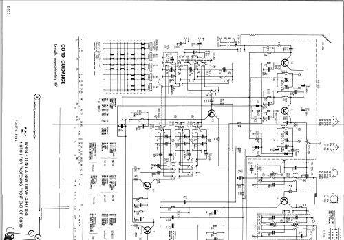
Clicca sulla miniatura dello schema per richiederlo come documento gratuito.
- Numero di transistor
- 12
- Semiconduttori
- BF255 BF240 BF241 BF241 BF241 BF241 BF241 BC108 BC109 BC181 AC187 AC188 BA124 1N60 AA112 AA112 BZ102
- Principio generale
- Supereterodina (in generale); ZF/IF 460/10700 kHz
- N. di circuiti accordati
- 7 Circuiti Mod. Amp. (AM) 10 Circuiti Mod. Freq. (FM)
- Gamme d'onda
- Onde medie (OM), 2 gamme di onde corte (2 x OC) e MF (FM).
- Tensioni di funzionamento
- Batterie / presa di alimentazione supplementare / D: 6 x 1.5 / DC 9 Volt
- Altoparlante
- AP magnetodinamico (magnete permanente e bobina mobile)
- Radiomuseum.org
- Modello: Transistor 865 Mariner - Grundig Radio-Vertrieb, RVF,
- Forma
- Apparecchio portatile > 20 cm (senza la necessità di una rete)
- Dimensioni (LxAxP)
- 380 x 235 x 105 mm / 15 x 9.3 x 4.1 inch
- Annotazioni
-
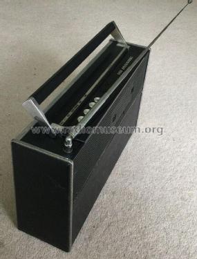
A portable AM/FM transistor radio with FM (88-108MHz), MW, SW and MSW (Trawler Band).
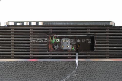
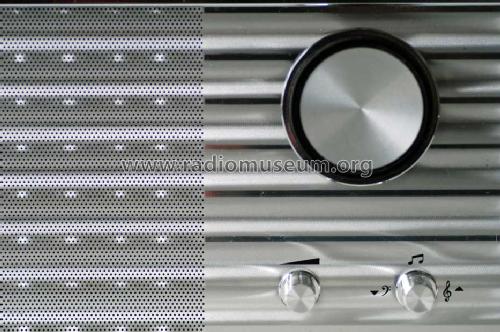
Mains power with removable power supply TN4 (110-125 / 220-240), or TN12A (110 / 220V) equipped with an additional transistor AD162. Batteries 6 x 1.5V D cells. With push buttons for AFC and dial illumination (permanently on when powered by the PSU), battery condition meter, volume control and tone control (which pulls out/pushes in to cut/boost bass), behind a sliding door on the back, a switch for PSU/battery power, DIN socket, earphone socket, an additional 9 volt power jack and terminals for FM and AM antennae and earth.See also the earlier Transistor 860 Mariner TR860 with different cabinet style. Also similar to the Grundig Yacht Boy N210 which has LW in place of Trawler Band.
- Letteratura / Schemi (1)
- -- Schematic
- Letteratura / Schemi (2)
- - - Manufacturers Literature (Grundig Transistor 865 Mariner repair manual dated 1970)
- Autore
- Modello inviato da Antonio Martins-Pais. Utilizzare "Proponi modifica" per inviare ulteriori dati.
- Altri modelli
-
In questo link sono elencati 6213 modelli, di cui 5446 con immagini e 4211 con schemi.
Elenco delle radio e altri apparecchi della Grundig (Radio-Vertrieb, RVF, Radiowerke); Fürth/Bayern
Collezioni
Il modello Transistor fa parte delle collezioni dei seguenti membri.


