Capaci Tester IT-22
Heathkit (Brand), Heath Co.; Benton Harbor (MI)
- Land
- USA
- Hersteller / Marke
- Heathkit (Brand), Heath Co.; Benton Harbor (MI)
- Jahr
- 1963 ?
- Kategorie
- Service- oder Labor-Ausrüstung
- Radiomuseum.org ID
- 87680
-
- anderer Name: Heath Company
Klicken Sie auf den Schaltplanausschnitt, um diesen kostenlos als Dokument anzufordern.
- Anzahl Röhren
- 1
- Röhren
- 1629
- Wellenbereiche
- - ohne
- Betriebsart / Volt
- Wechselstromspeisung / 105-125 Volt
- Lautsprecher
- - - Kein Ausgang für Schallwiedergabe.
- Material
- Metallausführung
- von Radiomuseum.org
- Modell: Capaci Tester IT-22 - Heathkit Brand, Heath Co.;
- Form
- Tischmodell, Zusatz nicht bekannt - allgemein.
- Abmessungen (BHT)
- 7.75 x 4.687 x 4.125 inch / 197 x 119 x 105 mm
- Literatur/Schema (1)
- -- Schematic
- Autor
- Modellseite von Hinrich Grensemann † 15.5.16 angelegt. Siehe bei "Änderungsvorschlag" für weitere Mitarbeit.
- Weitere Modelle
-
Hier finden Sie 717 Modelle, davon 700 mit Bildern und 507 mit Schaltbildern.
Alle gelisteten Radios usw. von Heathkit (Brand), Heath Co.; Benton Harbor (MI)
Sammlungen
Das Modell Capaci Tester befindet sich in den Sammlungen folgender Mitglieder.
Forumsbeiträge zum Modell: Heathkit Brand,: Capaci Tester IT-22
Threads: 3 | Posts: 3
Gemäss den Unterlagen im Web ist der Heathkit Capaci Tester IT-22 für 115 (105 - 125 V) Wechselspannung konstruiert, für die in den USA übliche Netzspannung.
Nun steht auf dem Typenschild meines Geräts IT-22E
Die Vermutung, dass das Gerät mit Suffix E mit einem für die europäische Netzspannung von 220 V ausgelegten Netztransformer ausgerüstet ist, bestätigte sich.
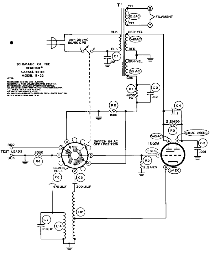
Aus der Sockelbeschaltung des magischen Auges 1629 mit einer Heizspannung von 12.6 V konnte ich entnehmen, dass an den Pins 2 und 7 diese Spannung anliegen sollte.
Und siehe da, beim Hochfahren mit dem Regeltransformator fand sich bei 115 V eine Heizspannung von über 6 V und das magische Auge blieb dunkel, beim Hochfahren auf 220 V leuchtet das magische Auge grün auf und die an den Pins gemessene Heizspannung beträgt knappe 13 V.
Somit kann davon ausgegangen werden, dass Geräte mit dem Suffix E (IT-22E) zum Betrieb am 220 V Netz vorgesehen sind und direkt am europäischen Lichtnetz betrieben werden können.
Aber dennoch: Vorsicht bei der ersten Inbetriebnahme, um vor Überraschungen gefeit zu sein.
Lieber Gruss
Martin Bösch
Martin Bösch, 27.Jul.24
In meinem Fundus befand sich schon lange ein Heathkit IT-22E Capaci Tester, den ich einmal in Betrieb genommen habe. Inzwischen ist die Anleitung im Web verfügbar, Joe Sousa hat die Funktionsweise in englischer Sprache bestens beschrieben, deshalb nur kurz:
- Das Gerät wird vorsichtig unter Spannung gesetzt, mit dem Betriebsschalter in der Position SHORT CHECK (oder auch OPEN CHECK) leuchtet das magische Auge nach der Aufwärmzeit auf. Das amerikanische Originalgerät verlangt 115 V Wechselspannung. Bei meinem in der Schweiz im Einsatz gewesenen Gerät tat sich bei dieser Spannung noch nichts, nach vorsichtiger Spannungserhöhung mit dem Regeltrafo beginnt das magische Auge etwas unterhalb 220 V grün zu leuchten.
- Kondensatoren können (auch in der Schaltung) auf Kurzschluss und Unterbruch getestet werden, gemäss Manual ist es egal, welcher Test zuerst erfolgt, Joe empfiehlt zuerst die Kurzschlusstestung, was Sinn macht.
- Kurzschlusstestung SHORT: In der Schalterposition SHORT CHECK ist der Fächer des magischen Auges offen.
In der Position SHORT TEST schliesst es sich bei einem brauchbaren Kondensator ohne Kurzschluss, wenn das magische Auge offen bleibt, hat der Kondensator einen Kurzschluss und gehört entsorgt.
Getestet wird mit einer Frequenz von 60 Hz, am europäischen Netz 50 Hz, der Netzfrequenz.
Ein Kondensator unter 1 μF führt zum Schluss des Auges, höhere Kapazitäten schliessen das magische Auge nur teilweise; Kapazitäten über 20 μF erscheinen als Kurzschluss und führen zum Öffnen des magischen Auges. - Unterbruch-Testung OPEN: in der Schalterposition SHORT CHECK schliesst sich das magische Auge.
In der Position OPEN TEST schliesst sich bei einem Kondensator von über 50 pF das magische Auge. Wenn sich das magische Auge öffnet, ist der Kondensator offen resp. es besteht ein Unterbruch.
Getestet wird mit einem auf 19 MHz schwingenden Hartley Oszillator und einem Schwingkreis, über den dem Oszillator Energie entzogen wird, die Schwingungen setzen aus, die Gittervorspannung wird reduziert und das magische Auge öffnet sich. Ein brauchbarer Kondensator verstimmt den Kreis, der die Energie entzieht, der Oszillator schwingt weiter und das magische Auge schliesst sich. - Zuletzt wird in der Schalterposition AC OFF die Netzspannung abgeschaltet und auch der Kondensator durch Kurzschliessen der Anschlüsse entladen.
- Elektrolytkondensatoren können nur auf Unterbruch untersucht werden, die Short - Testung zeigt immer einen Kurzschluss an.
Ich hoffe, ich habe es richtig hinbekommen und die glücklichen Besitzer eines IT-22 kommen mit dem Gerät klar,
lieber Gruss
Martin Bösch
Martin Bösch, 27.Jul.24
Fellow Radiophiles,
I present here a functional analysis for each position of the rotary switch of the IT-22 capaci-tester. I don't have access to a manual, I am working with the schematic and a picture of the front panel.
I found a set of instructions for the very similar model Heathkit CT-1 at
http://www.nostalgickitscentral.com/heath/products/test/ct1.txt
Another description of the test capabilities is at
http://www.heathkit-museum.com/test/hvmct-1.shtml
According to this link, this tester does not check leakage or electrolytic caps. Note that the test signals used by the tester are all AC type signals at 19MHz for opens and 60Hz for shorts. No DC bias is provided for electrolytics. The primary usefulness of this tester is the ability to test non-electrolytic paper, mica, film or ceramic capacitors for shorts or opens, without removing them from the Radio or TV.
It would be good to see a set of operating instructions for this IT-22 set.
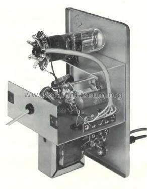
Before I start on the general functionality, note that there is no DC power supply. The eye target anode and triode plate only work on the positive halves of the 540VAC power transformer secondary. The 55VAC winding provides a bias that is negative when the tube is active on the positive halves of the 540VAC winding. One drawback of this approach is that the eye pattern may not be as sharp as with a DC supply.

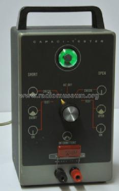
I will refer to the switch drawing in the schematic, and rotate the switch clock-wise, starting from the OFF position. The front panel shows 5 switch positions with OFF at the center:
Short Test
Short Check
AC OFF
Open Check
Open Test
 Position Short Test The control grid is connected to the Red test lead and to the negative bias source provided by R1 and R2, via taps 4+5+10. This is a DC test because the Hartley oscillator is disabled, and the test is conducted during the positive half cycles of the 540VAC power transformer winding. A shorted input capacitor opens the eye. A good capacitor under 1uF will close the eye. The absence of a capacitor at the leads also closes the eye. The reactance of 1uF at 60Hz is 2.6k, which will start to load the R1R2 significantly. Above 1uF, the eye should start to open up due to the low capacitive reactance. The CT-1 instructions at the link above say that this test works for capacitances up to 20uF. Larger capacitances look like a short.
Position Short Check The control grid is grounded by taps 5+9. The triode plate and deflection anode go to a low voltage and open the eye. The Red test lead is open. The LC circuitry at the cathode is prevented from spurious oscillation by the R4=3.3K damping resistor. This test is meant to warm up the unit from the off position and the capacitor should not be tested until the eye is completely open in this position.
Position AC OFF The slaved power switch in series with the power transformer is open. A 3.3k resistor shunts away any charge present at the capacitor to be tested.
Position Open Check Switch taps 9+10+11 are grounded, thus shorting out the cap under test without any current limiting resistor, before any tests are conducted. The control grid is tied to C5 via switch taps 5+2, thus completing the feedback loop of a Hartley oscillator via L1B. The -8V DC grid leak bias that develops at the grid due to the Hartley oscillation, cuts off the triode. The resulting high voltage at the triode plate and deflecting anode close the eye completely. The oscillation frequency for the similar CT-1 model is19MHz. This test is meant to warm up the unit from the off position and the capacitor should not be tested until the eye is completely closed in this position.
Position Open Test The Hartley oscillator loop is still closed by taps 5+2. The oscillator coil secondary L1A is now tied to the active RED test input via C6=470pF. R4=3.3k is still in parallel with the capacitor input. A non-shorted capacitor greater than 50pF at the input will lower the oscillating frequency to a point that oscillator amplitude is much lower, or extinguished. The -8V grid leak bias is thus reduced and the eye closes. The reduction in oscillation amplitude with at lower frequencies is due to the Q of the inductor being dominated by series resistance of the L1 inductor, in particular the L1a winding that is loaded by the cap under test. A shorted cap will also close the eye, so the short test should be done first.
Corrections and comments are invited.
Regards,
-Joe
Joe Sousa, 10.Mar.10


