Digital Multimeter / Counter 5306A
Hewlett-Packard, (HP); Palo Alto, CA
- Produttore / Marca
- Hewlett-Packard, (HP); Palo Alto, CA
- Anno
- 1973
- Categoria
- Strumento da laboratorio
- Radiomuseum.org ID
- 122496


The measuring system 5300B


Clicca sulla miniatura dello schema per richiederlo come documento gratuito.
- Numero di transistor
- A semiconduttori.
- Semiconduttori
- Tensioni di funzionamento
- Alimentazione a corrente alternata (CA) / 115; 230 Volt
- Altoparlante
- - - Nessuna uscita audio.
- Materiali
- Mobile di metallo
- Radiomuseum.org
- Modello: Digital Multimeter / Counter 5306A - Hewlett-Packard, HP; Palo Alto
- Forma
- Soprammobile compatto/con bordi arrotondati/midget senza pulsantiera/tastiera.<= 35 cm (Sometimes with handle but for mains only).
- Dimensioni (LxAxP)
- 160 x 93 x 265 mm / 6.3 x 3.7 x 10.4 inch
- Annotazioni
-
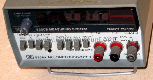
The 5306A Multimeter/Counter is a high accuracy measuring system with the integrated 5300B Measuring part with a large bright 8 digit led display and a resolution of 0.1 Hz.
The 5306A Multimeter/Counter is part of the measuring system HP 5300.
Functions of the 5300B Measuring System: DCV, ACV, FREQ, OHM ith range: 10, 100, 1000V; 10K TO 10M OHMS (Flag light on voltage present). AC can vary +13 to - 17% and 48 to 440 Hz. Line frequency 44 - 440 HZ (good for aircraft power).
Such Instruments are today refurbished by Agilent.
- Peso netto
- 2.5 kg / 5 lb 8.1 oz (5.507 lb)
- Prezzo nel primo anno
- 450.00 $
- Bibliografia
- Hewlett-Packard Journal, June 1973, page 7 to 15
- Autore
- Modello inviato da Ernst Erb. Utilizzare "Proponi modifica" per inviare ulteriori dati.
- Altri modelli
-
In questo link sono elencati 399 modelli, di cui 367 con immagini e 139 con schemi.
Elenco delle radio e altri apparecchi della Hewlett-Packard, (HP); Palo Alto, CA
Collezioni
Il modello Digital Multimeter / Counter fa parte delle collezioni dei seguenti membri.
Discussioni nel forum su questo modello: Hewlett-Packard, HP;: Digital Multimeter / Counter 5306A
Argomenti: 1 | Articoli: 5
Unfortunately my 5306A Multimeter/Counter with the measuring System 5300B shows only zeros ... I would be grateful if somebody can upload schematics ...
But here what I found published in the Hewlett-Packard Journal from June 1973 on page 7 to 15: HP published it and therefore there should not be a problem to publish this tied to the instrument.
DMM and DAC Modules Expand Low-Cost
Measuring System
A five-digit multimeter/ counter module and a three-digit digital-to-analog converter module are new members of the 5300 Measuring System joining the mainframe, battery pack, and four timer/counter modules previously available.
by James F. Horner, Lewis W. Masters, and P. Thomas Mingle
Altough basically a counting system, the 5300 Measuring System, as its name implies, isn't limited to counter measurements. The 5300A mainframe, with its six-digit 10 MHz counter, counts a signal presented to it by the snap-on functional module, which contains circuits for function selection and signal shaping. Therefore, any quantity that can be converted to an appropriate frequency by a snap-on module can be measured by the mainframe.
The first four snap-on modules were designed for counter-timer measurements. The newest, Model 5306A Multimeter/Counter (Fig. 1), is the first to apply the inherent flexibility of the mainframe to other types of measurements. It offers functions of dc volts, ac volts, ohms, and frequency, all the functions usually found in digital multimeters plus an extra one, frequency.
Another new module, Model 5311A Digital-to-Analog Converter, fits between the mainframe and the snap-on functional module. It converts any three digits of the 5300A display to a proportional analog voltage output. It can be used with any snap-on module, and with or without the 5310A Battery Pack, which is also an "in-between" module. The design of Model 5311A is described on page 11.
Four-Digit Accuracy, Five-Digit Resolution
Model 5306A Multimeter/Counter measures dc voltage in three ranges: ±10 V, ±100 V, and ±1000 V full scale. Ac voltage is measured in ranges of 10 V, 100 V, and 1000 V, and resistance-measurement ranges are 10 kO, 100 kO, and 10 MO full scale.
Accuracy specifications are essentially those of a four-digit multimeter. However, for reasons to be explained later, Model 5306A's fifth digit is a full digit, not just an overrange digit, so measurement resolution and dynamic range are those of a five-digit instrument. The effect is to make every range on the 5306A equivalent to two ranges on a typical four-digit meter. For example, in the 100 V range the resolution is 1 mV, so measurements can be made from millivolts to 100 V without changing ranges.
When maximum resolution isn't needed and more than two measurements per second are desirable -- for example, when displaying the results of a coarse adjustment --- a FAST sample mode can be selected. Measurements are then ten times faster. Accuracy and resolution are both four digits.
In frequency measurements, the 5306A has the full six-digit accuracy and resolution built into the 5300A mainframe. Frequency range is 40 Hz to 10 MHz. The FAST sample mode can also be used for frequency measurements, again with one less digit of resolution.

Fig. 1
Two new modules tor the 5300 Measuring System are Model 5306A Multimeter/ Counter (bottom module of instrument in foreground) and Model 5311A Digital-to-Analog Converter (center module). The Multimeter/Counter measures dc voltag, ac voltage, resistance, and frequency. Other elements of the system are the mainframe (top module) four counter/timer modules and a battery pack.
Design Philosophy
In designing a four-digit multimeter snap-on functional module for a six-digit counter mainframe, many questions had to be answered. The most obvious was what to do with the extra two digits in the mainframe.
One digit was easy to dispose of. The designers of the mainframe had foreseen that some future module might require a polarity indication in the display, and had made it easy to generate a minus sign in place of the most significant digit. The 5306A uses the minus sign for dc voltage measurements.
The next most significant digit could have been used as an overrange digit, like the 1/2 digit of a 4 1/2 digit multimeter. But this would have been wasteful because a full digit (that is, 0 through 9 instead of just 0 or 1) could be displayed in that position. It was suggested that the 5306A might be designed with five-digit accuracy. However, the extra cost wasn't compatible with the concept of the 5300 Measuring System as a low-cost laboratory and field instrument. The accuracy specification was finally fixed at 0.03 %, or +/- 3 counts error in the fourth significant digit.
Percent of Reading versus Percent of Range
Errors in a digital voltmeter fall into two categories: errors that must be specified as a percent of the actual reading and errors that must be specified as a percent of the range or full-scale reading. Attenuator coefficient uncertainty and reference drift cause percent of reading errors. Input amplifier zero drift causes percent of range errors.
The user, of course, is interested in the total error as a percent of his reading. Shown in Fig. 2 is a plot of reading versus percent error for a four-digit measurement. The limiting errors are the zero error and the resolution. If the resolution of the measurement could be extended and the zero error reduced, then while the reference accuracy (the accuracy of a full-scale reading] would remain the same, the dynamic range and the accuracy of smaller readings would be improved.

Fig. 2
Error limit versus reading tor typical tour-digit and five - digitvoltmeters. Percent - of - range errors (i.e., zero drift and resolution) dominate the percent - ot - reading errors or reference accuracy (caused by attenuator inaccuracy or reference drift). In Model 5306A an extra digit of resolution and an auto-zero system greatly reduce percent-ot-range errors. Reference accuracy remains that of a tour-digit instrument, but in other respects it is a lull five-digit meter. Each range is equivalent to two ranges on the usual four-digit voltmeter.
Improved resolution requires extra digits, of course, but for the 5306A an extra digit was already there. The decision, therefore, was to use a voltage-to-frequency converter with five-digit dynamic range and resolution, and to develop an auto-zero system for it that would reduce zero drift caused by time or temperature effects to a level compatible with a five-digit instrument.
The result is shown in Fig. 2, which compares the error limit for the 5306A with that of typical four-digit and five-digit voltmeters. The 5306A has four digit accuracy as a percent of reading, but its per cent of range errors are considerably reduced from the four-digit case. Thus the fifth digit is a full digit. The 5306A is a five-digit voltmeter with four-digit reference accuracy.
The design of the 5306A indicates that in some cases eliminating mechanical attenuators --- that is, ranges --- in favor of extra digital readouts may be justified from a cost/performance viewpoint.
Voltage-to-Frequency Converter
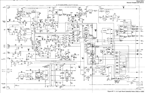
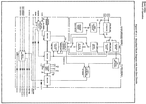
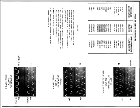
Fig. 3 is a block diagram of the 5306A Multimeter/Counter. The voltage-to-frequency converter is essentially the same as that used in the 5326B/5327B Timer/Counter/DVM1. Fig. 4 is its circuit diagram. The converter is actually two essentially identical converters, one for positive input voltages and one for negative, sharing the same integrator. For clarity, only the positive converter is shown completely in Fig. 4.
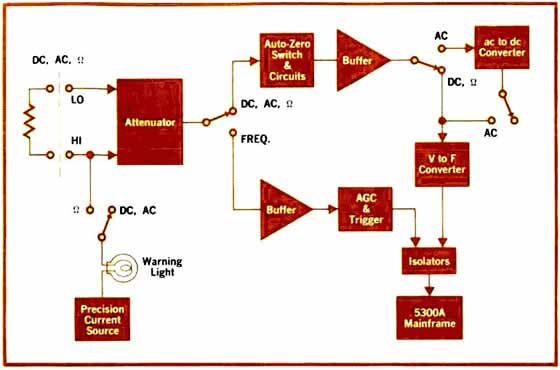
Fig. 3
5306/4 is floating and isolated from the grounded mainframe. For frequency measurements, the input signal is shaped by the 5306A and measured by the mainframe with six-digit accuracy and resolution.
Operation of the converter for a positive input voltage Vin is as follows. Vin goes to the integrator, and the integrator output is compared with a threshold voltage Vth. If the integrator output is more negative than Vth, then when the next clock pulse occurs (there's a clock pulse every five microseconds) the Q output of the flip-flop goes to its high state, routing the reference current IR, which previously flowed through CR2, now through CR1 into the summing node of the integrator.

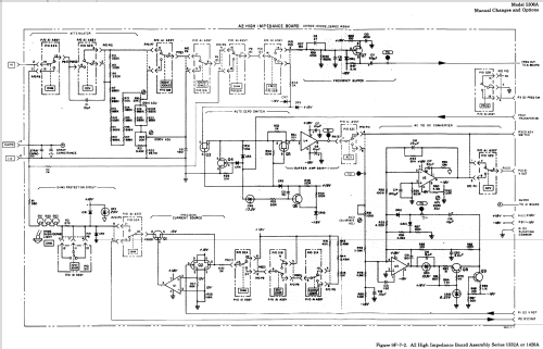
Fig. 4
Voltage-to-frequency converter generates a frequency proportional to a positive or negative dc input voltage. (Omitted for clarity are comparator, flip-flop, and switch for negative inputs.) The auto-zero system derives a zero-correction voltage while the previous measurement is being displayed, then applies this voltage to the integrator input during the next measurement phase.
When the Q output of the flip-flop is in its high state, clock pulses are gated to the output. Thus the output signal consists of bursts of clock pulses at the frequency fin, which is the counter time-base frequency of 10 MHz divided by 50, or 200 KHz. The ratio of the average converter output frequency, fout, to the frequency fin is the proportion of time that the Q output is in its high state. This duty cycle, "8", is proportional to Vin, as the following equations show.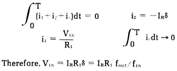
The reference for the measurement is the reference current IR. This current is derived in a straight forward resistor-amplifier circuit from a stable voltage generated by a pair of feedback-stabilized zener diodes. It is stable within about 10 ppm per degree C. Thus its stability is consistent with the overall reference accuracy specification of +/- 0.03%.
The V-F converter has five-digit resolution and range. However, zero drift from various sources would normally limit it to four-digit use. The autozero system reduces this drift to a level consistent with five-digit accuracy.
Auto-Zero System
The 5306A auto-zero system operates in two phases. During the display phase an electronic switch, represented by S1 and S2 in Fig. 4, disconnects the input voltage from the input amplifier and shorts the input amplifier to ground.
Any zero offset in the system causes a non-zero slope on the output of the integrator. The auto-zero circuit detects this slope and generates a correction voltage that is applied to the integrator to drive the integrator slope to zero. The closed loop residual error is less than 20 microvolts.
During the measurement phase the electronic switch disconnects the short on the input amplifier and reconnects the input voltage. A sample-and-hold circuit on the output of the auto-zero circuit holds the correction voltage derived during the display phase to compensate the measurement system for any zero error (Fig. 5).
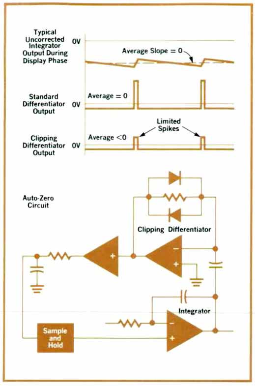
Fig. 5
Integrator output is ditterentiated to detect non-zero slope and derive the zero-correction voltage. Because the average output of a standard differentiator would be zero, a clipping differentiator is used.
The critical part of the auto-zero circuit is the detection of any residual slope on the output of the integrator. A simple differentiator could accomplish this except that the average slope on the output of the integrator is zero. The reason it is zero is that once the output of the integrator has reached the designated voltage reference, the reference current is switched on, rapidly driving the voltage back in the opposite direction. As a result, the average output of a standard differentiator would also be zero. This situation is illustrated in Fig. 5.
To operate effectively, the auto-zero circuit needs to reject the high spikes caused by the switching on of the reference current. The standard differentiator was modified into a clipping differentiator (Fig. 5), which limits the differentiation excursion possible.
The resulting output contains a dc component proportional to the residual zero error. This output is filtered and applied to the integrator through the sample-and-hold circuit to zero the system.
Ernst Erb, 15.Dec.07