Tube Tester 6000
Hickok Electrical Instrument Co.; Cleveland, OH
- País
- Estados Unidos
- Fabricante / Marca
- Hickok Electrical Instrument Co.; Cleveland, OH
- Año
- 1957–1962
- Categoría
- Aparato de medida y servicio (Equipo de laboratorio).
- Radiomuseum.org ID
- 113444
-
- alternative name: Hickock


aus ebay, #115535058265, Verkäufer dr_nine

aus ebay, #115535058265, Verkäufer dr_nine


aus ebay, Verkäufer riatla


Haga clic en la miniatura esquemática para solicitarlo como documento gratuito.
- Numero de valvulas
- 2
- Gama de ondas
- - no hay
- Tensión de funcionamiento
- Red: Corriente alterna (CA, Inglés = AC) / 110 Volt
- Altavoz
- - - No hay salida de sonido.
- Material
- Madera
- de Radiomuseum.org
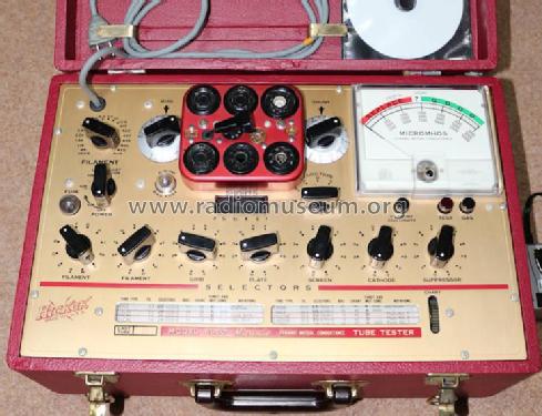
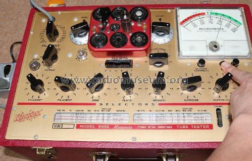
- Modelo: Tube Tester 6000 - Hickok Electrical Instrument
- Forma
- Sobremesa, caja, normalmente con tapa (panel no inclinado).
- Ancho, altura, profundidad
- 265 x 185 x 425 mm / 10.4 x 7.3 x 16.7 inch
- Anotaciones
- Vereinfachtes Modell des 600; kleiner und leichter gebaut, für Servicezwecke.
- Peso neto
- 7.3 kg / 16 lb 1.3 oz (16.079 lb)
- Mencionado en
- Alan Douglas, Tube Testers and Classic Electronic Test Gear
- Otros modelos
-
Donde encontrará 155 modelos, 139 con imágenes y 46 con esquemas.
Ir al listado general de Hickok Electrical Instrument Co.; Cleveland, OH
Colecciones
El modelo Tube Tester es parte de las colecciones de los siguientes miembros.
Contribuciones en el Foro acerca de este modelo: Hickok Electrical: Tube Tester 6000
Hilos: 1 | Mensajes: 10
Gentle tube enthusiasts,
together with fellow Dale Spear, I am working on a project which involves good knowledge of the circuitry and theory of operation of 6000, 6000A and 6005 tube testers.
I have three main concerns:
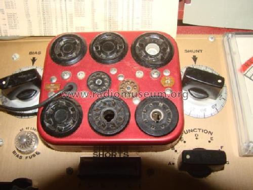
1) the user's manual states that the seven sockets' contact dials have fourteen positions. However, other literature mentions twelve positions. Do they perhaps have two "standby" (= disconnected) positions, which would solve the discrepancy?
2) I particularly seem to have problems with dial 2. It should be marked 1-2-3-R-S-T-U-V-W-X-Y-Z but in the tube charts I consistently find as well a P position. Which socket's contact is connected when it is turned in P position, or which other operation is performed?
3) The "FUNCTION" switch is said to have eight positions. However, the positions used in tube testings seem to be only five: A-B-C-D and F. As long as I understand, A is used for amplifiers' tests, C for diodes' tests and D for rectifiers' tests. But I couldn't find any literature on what B and F functions are used for and what they specifically do. Does anyone have any clue?
Thanks for reading.
Marco Gilardetti, 09.Oct.09