- Pays
- Australie
- Fabricant / Marque
- His Master's Voice (HMV, H.M.V.), EMI (Australia) Ltd.; Sydney, NSW
- Année
- 1947/1948
- Catégorie
- Radio - ou tuner d'après la guerre 1939-45
- Radiomuseum.org ID
- 184896
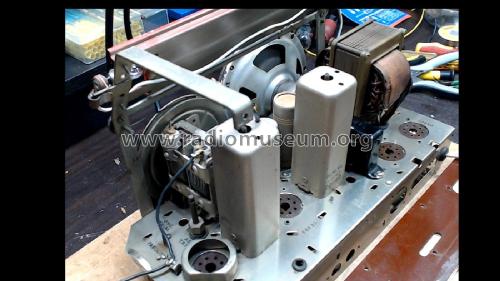
Chassis after clean.
Cliquez sur la vignette du schéma pour le demander en tant que document gratuit.
- No. de tubes
- 4
- Principe général
- Super hétérodyne (en général); FI/IF 457.5 kHz; 1 Etage(s) BF
- Circuits accordés
- 6 Circuits MA (AM)
- Gammes d'ondes
- PO uniquement
- Tension / type courant
- Alimentation Courant Alternatif (CA) / 40-50 Hz, 200-220; 221-240; 241-250 Volt
- Haut-parleur
- HP dynamique à aimant permanent + bobine mobile / Ø 5 inch = 12.7 cm
- Puissance de sortie
- 1.5 W (max.)
- Matière
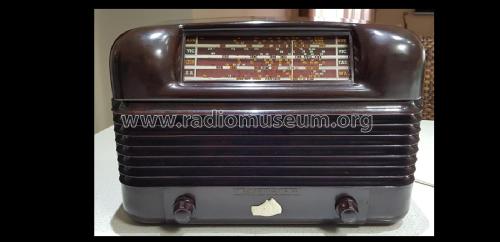
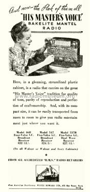
- Boitier en bakélite
- De Radiomuseum.org
- Modèle: 46B Ch= A436B/S - His Master's Voice HMV, H.M.V.
- Forme
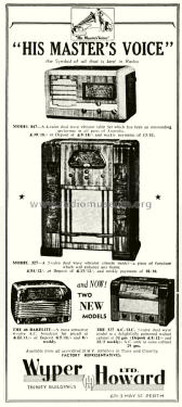
- Modèle de table sans poussoirs, modèle cheminée
- Remarques
-
Cabinet colours: walnut, walnut with ivory grille, green with ivory or all cream.
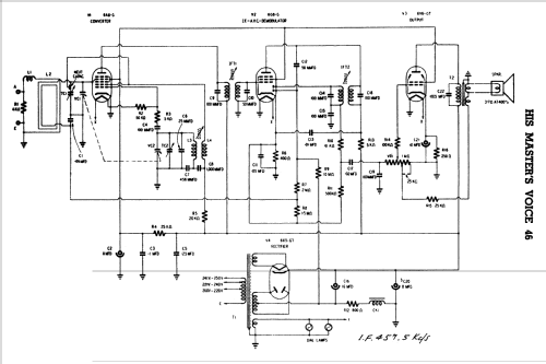
CIRCUIT DESCRIPTION (from service manual)
This model is a four-valve mains operated broadcast superheterodyne. It normally operates from a self-contained loop aerial which is provided with primary coupling for connection of an aerial/earth system. The primary circuit incorporates a loading inductance and damping resistor in order to reduce signal frequency tracking error to a minimum when an external aerial/earth system is connected.
The signal frequency tuned circuit is connected to a Pentagrid Converter; Oscillator voltage on the signal grid of this valve is neutralised by means of a small wire capacitor connected from oscillator plate to signal grid. The oscillator inductance is permeability tuned and has a fixed padder capacitance.
The converter valve is transformer coupled to the pentode section of a duo-diode pentode valve, the output of which is in turn transformer coupled to the demodulator diode, the other diode being capacity coupled to the plate circuit and functions as an A.V.C. rectifier. Both I.F. transformers are permeability tuned and have fixed capacitors. A resistive network across the H.T. filter choke and series resistor provides delay voltage for the A.V.C. diode and standing bias for the converter valve. A.V.C. voltage is applied to the converter valve whilst the I.F. valve is operated with fixed bias. The demodulator circuit is coupled to the potentiometer volume control, the output of which is taken to the grid of the beam power output valve.
The power output of this valve is limited by operating the screen at a reduced voltage. The output stage is transformer coupled to the voice coil of a permagnetic speaker. A tertiary winding on the output transformer provides inverse feedback voltage which is fed back to the input circuit of the output stage through a tap on the volume control.
High tension voltage is supplied by a full wave rectifier, the output of which is filtered by a choke in the negative side.
See also wooden cabinet version, Model 46W.
- Prix de mise sur le marché
- 21.50 AUS £
- Source du schéma
- Australian Official Radio Service Manual Vol. VI
- Littérature
- Radio Electrical WEEKLY (New Products, 12/1/1948.)
- Schémathèque (1)
- -- Original-techn. papers. (Service Manual.)
- Schémathèque (2)
- Australian Official Radio Service Manual AORSM (Volume 6, 1948 (for 1947 models).)
- Schémathèque (3)
- Mingay's "Radio Diagram & I.F. Index
- Auteur
- Modèle crée par Stuart Irwin. Voir les propositions de modification pour les contributeurs supplémentaires.
- D'autres Modèles
-
Vous pourrez trouver sous ce lien 589 modèles d'appareils, 414 avec des images et 284 avec des schémas.
Tous les appareils de His Master's Voice (HMV, H.M.V.), EMI (Australia) Ltd.; Sydney, NSW