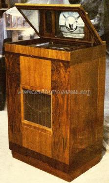
Television HMV901 Console
HMV (Brand), His Masters Voice, The Gramophone Company Ltd.; Middlesex
- Pays
- Royaume Uni
- Fabricant / Marque
- HMV (Brand), His Masters Voice, The Gramophone Company Ltd.; Middlesex
- Année
- 1936–1939
- Catégorie
- Récepteur de télévision ou moniteur
- Radiomuseum.org ID
- 282385

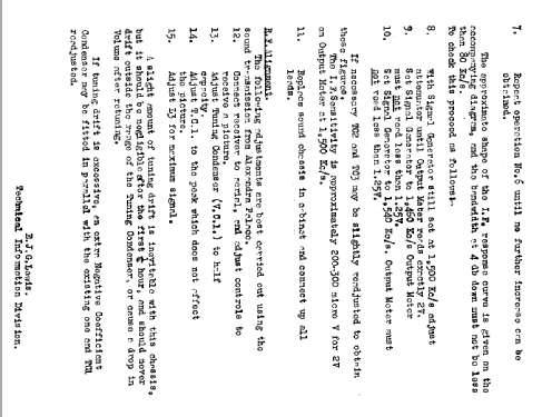

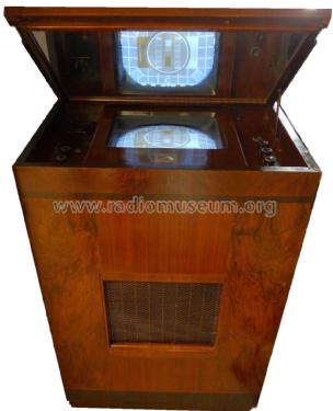
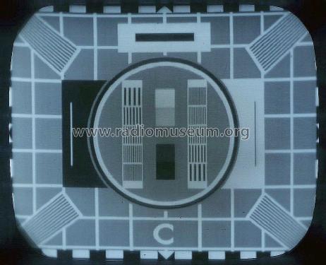
HMV901 displaying Test Card C

HMV 901 Close up Screen image of Test Card C

The aerial plug and cable are massive.
Cliquez sur la vignette du schéma pour le demander en tant que document gratuit.
- No. de tubes
- 22
- Lampes / Tubes
- MSP4 MSP4 MSP4 MSP4 MSP4 MSP41 D42 X41 VMP4G MHD4 N41 MSP4 MSP4 D42 MS4B MS4B N41 N41 U12 U12 U16 6/4 or 6/6
- Principe général
- Récepteur TRF avec détection diode; FI/IF 1500 kHz; 2 Etage(s) BF
- Gammes d'ondes
- Bandes en notes
- Tension / type courant
- Alimentation Courant Alternatif (CA) / 200-250 Volt
- Haut-parleur
- HP dynamique oval à aimant permanent
- Matière
- Boitier en bois
- De Radiomuseum.org
- Modèle: Television HMV901 [Console] - HMV Brand, His Masters Voice,
- Forme
- Console de forme générique
- Dimensions (LHP)
- 24 x 37 x 16 inch / 610 x 940 x 406 mm
- Remarques
-
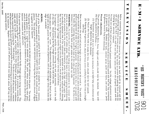
In 1934 the Marconi-EMI Television Company Ltd was formed bringing together the vision transmitter technologies of the Marconi Company with the television studio equipment and receiver technologies of the EMI Company. It was this company that provided the design and technology for Britain's television service using 405 lines and 25 frames/sec interlaced.
Transmissions commenced in November 1936 and continued until it was closed in the early 1980s. The first dedicated television receivers designed by EMI were the HMV 901 and the Marconi 702. These sets were identical except for cosmetic differences in the cabinets.
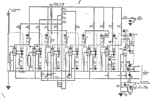
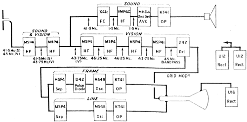
The vision receiver is a straight TRF tuned to 45MHz. The sound receiver shares the first two RF stages and follows them with a superhet using an IF of 1.5MHz to receive the 41.5MHz signal.
- Prix de mise sur le marché
- 99.75 £
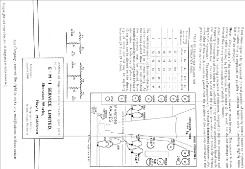
- Littérature
- Wireless World (The), London (WW, 79) (January 29th 1937)
- Auteur
- Modèle crée par Peter Scott. Voir les propositions de modification pour les contributeurs supplémentaires.
- D'autres Modèles
-
Vous pourrez trouver sous ce lien 429 modèles d'appareils, 340 avec des images et 244 avec des schémas.
Tous les appareils de HMV (Brand), His Masters Voice, The Gramophone Company Ltd.; Middlesex
Musées
Le modèle Television peut être vu dans les musées suivants.
Contributions du forum pour ce modèle: HMV Brand, His: Television HMV901
Discussions: 1 | Publications: 3
In 1934 the Marconi-EMI Television Company Ltd was formed bringing together the vision transmitter technologies of the Marconi Company with the television studio equipment and receiver technologies of the EMI Company. It was this company that provided the technology for Britain's television service in the years from 1936 through to the switch-off of the 405 line transmissions in the early 1980s.
The very first dedicated television receivers developed by this alliance were the HMV model 901 and the Marconi model 702. These sets were essentially identical but had differences in the veneering of the cabinet and the shape of the speaker grill so as to appeal to traditional customer loyalties for the two brands. The same design of television circuitry was also incorporated into a number of other sets carrying the HMV and Marconi names that included radios and gramophones.
Early cathode ray tubes (CRT) had considerable length due to their small deflection angles and large electron guns consequently set manufacturers often mounted the tube vertically in order to reduce the depth of cabinets. The picture is viewed through a mirror mounted in the lid.
A 1937 HMV901 television displays an image on its vertical cathode ray tube.
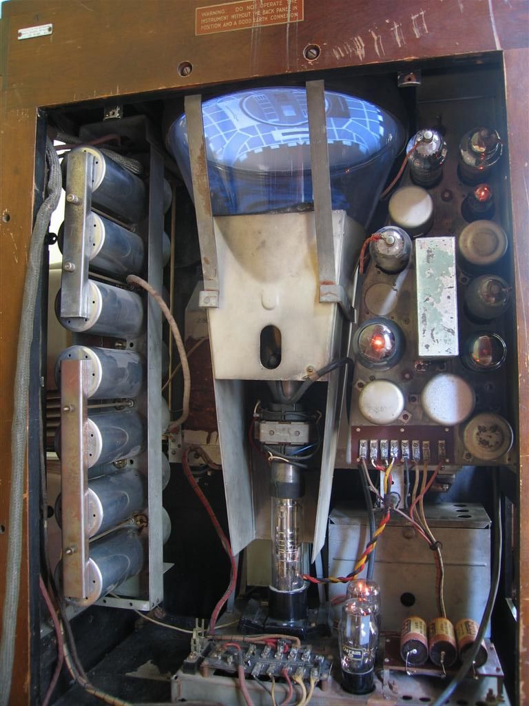
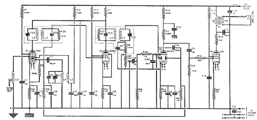
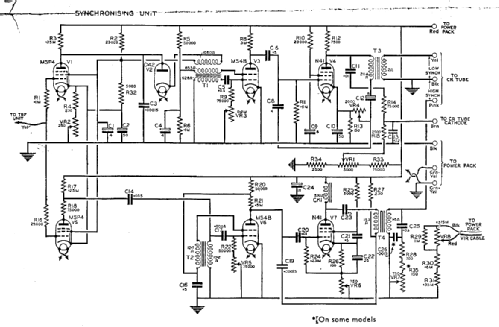
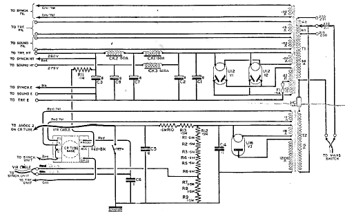
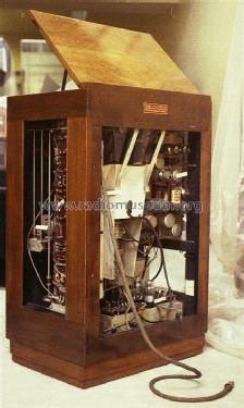
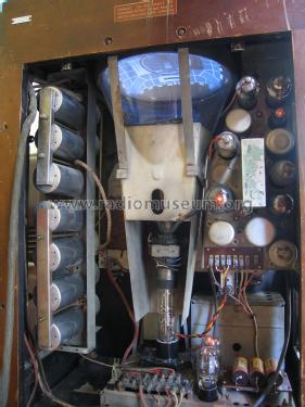
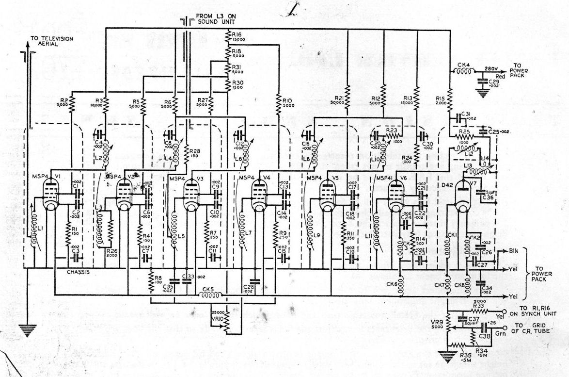
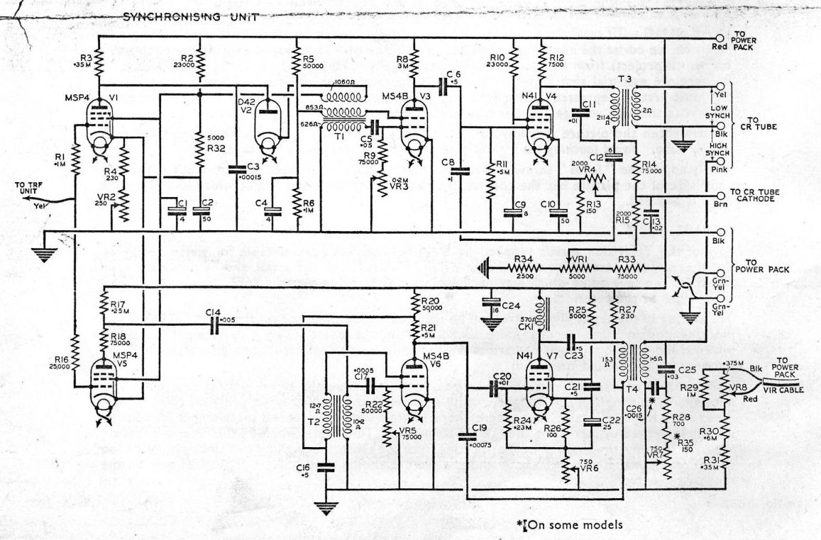
At this time there was only one television channel and one transmitting station. This set is designed with a straight (TRF) vision receiver tuned to 45 MHz. and consists of six RF pentodes and a diode detector. These are contained in the screening cans on the left. There is no video amplifier. The detector connects directly to the CRT. To the right of the CRT are the synch separator and line and frame timebases and on the floor of the cabinet is the power supply chassis. The 5000 volt supply for the CRT final anode is generated from a step up transformer from the mains and this and the EHT rectifier are located below the timebase chassis in a metal box behind the two brightly lit HT rectifiers. Only a small part of the sound receiver is visible in this picture. It is a superhetrodyne receiver tuned to 41.5MHz and shares the first two RF stages with the vision receiver and its RF connection can be seen between the second and third cans from the top.
TRF Section
Synch Unit (Timebases)
Sound Receiver
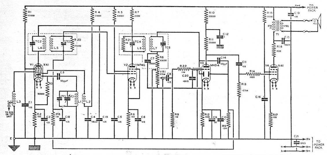
Power Supply

The test card image shows a slightly darkened central area and a concentrated dot in the greyscale blocks caused by ion burn. The CRT has no ion trap and no screen aluminising. The EMI service notes say "A slight amount of frame crushing at the lower end of the picture is standard but in special cases only, a frame linearity control can be added provided that the Frame circuits have been thoroughly investigated." This set has no frame linearity control and shows the "standard" crushing.

Another optional add-on was a picture centring coil or "push about coil" as EMI described it. This set had been fitted with one but it was found to distort the focus at the right side of the picture and adequate centring could be achieved simply by pushing the tube neck slightly to one side or another, thus shifting the screen within the rubber mask, so the coil was removed.
The Close Down of the 405 line Service
The 405 line broadcasts were closed down in 1984. The Queen gives her Christmas message just before the 405 line service was closed.

You can get an impression of the type of program that the BBC was producing at their Alexandra Palace station in London in 1937 HERE.
More information about the HMV901
More information on EMI television studio equipment
Pièces jointes
- HMV901 Rear View (127 KB)
- HMV901 TRF (174 KB)
- HMV901 Sync (166 KB)
- HMV901 Sound (96 KB)
- HMV901 Power Supply (99 KB)
- 405 Line Close Down (37 KB)
Peter Scott, 14.May.16