30 MHz Riometer calibrator
Homebrew - ORIGINAL; GB
- Country
- Great Britain (UK)
- Manufacturer / Brand
- Homebrew - ORIGINAL; GB
- Year
- 1964
- Category
- Radio module post 1925 (not a part, not a key)
- Radiomuseum.org ID
- 304503
Click on the schematic thumbnail to request the schematic as a free document.
- Number of Transistors
- 2
- Semiconductors
- Wave bands
- Short Wave (SW only)
- Power type and voltage
- Other, details in remarks or not known. / 6, 28 and 180 Volt
- Loudspeaker
- - - No sound reproduction output.
- Material
- Metal case
- from Radiomuseum.org
- Model: 30 MHz Riometer calibrator - Homebrew - ORIGINAL; GB
- Shape
- Tablemodel, Box - most often with Lid (NOT slant panel).
- Dimensions (WHD)
- 93 x 120 x 120 mm / 3.7 x 4.7 x 4.7 inch
- Notes
-
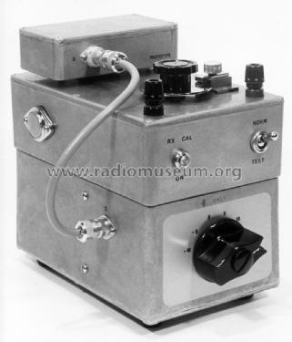
Calibrator for 30 MHz Riometer. (Relative Ionospheric Opacity Meter)
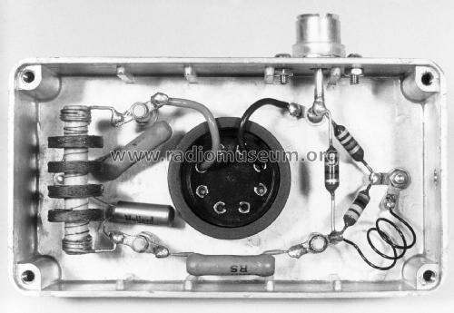
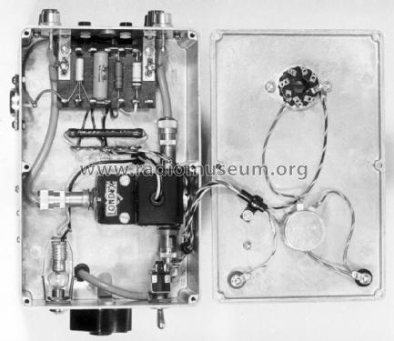
Home built in the UK by GM3NZI in 1964.The calibrator comprises a Zener diode noise generator, a coaxial antenna switch and a motorised attenuator. It is designed to calibrate the sensitivity of a receiver that records the intensity of galactic noise at around 30 MHz. At regular intervals the calibrator receives control signals from a clock that cause it to switch the receiver input from its antenna to the noise generator. The attenuator then steps successively through levels of +10 dB, +5 dB, 0 dB, -5 dB and -10 dB relative to the nominal galactic noise level. The coaxial switch then reconnects the receiver to its antenna to continue recording the galactic noise level.
Since the antenna is directed at the north celestial pole, it continues to receive radiation from the same area as the earth rotates on its axis. Hence the observed variations in received signal strength indicate the relative opacity of the ionosphere.
The Zener diode was selected for its stable long-term noise output and low temperature coefficient, and the noise generator is in a plug-in module that allows it to be checked against an absolute standard at intervals. There is provision to measure and adjust the diode current, and to rotate the attenuator manually for test purposes.
Input and output impedance 75 ohms.
DC power supplies:
180v regulated.
28v for Ledex solenoid.
6v for Londex relay.Built in three Eddystone die cast boxes.
- Net weight (2.2 lb = 1 kg)
- 0.7 kg / 1 lb 8.7 oz (1.542 lb)
- Author
- Model page created by Bruce Taylor. See "Data change" for further contributors.
- Other Models
-
Here you find 41 models, 19 with images and 7 with schematics for wireless sets etc. In French: TSF for Télégraphie sans fil.
All listed radios etc. from Homebrew - ORIGINAL; GB
Collections
The model 30 MHz Riometer calibrator is part of the collections of the following members.


