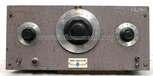
Audio Oscillator 200A
Hewlett-Packard, (HP); Palo Alto, CA
- Country
- United States of America (USA)
- Manufacturer / Brand
- Hewlett-Packard, (HP); Palo Alto, CA
- Year
- 1939–1946

- Category
- Service- or Lab Equipment
- Radiomuseum.org ID
- 82820
Click on the schematic thumbnail to request the schematic as a free document.
- Number of Tubes
- 5
- Main principle
- something special ? Please give information (notes)
- Wave bands
- - without
- Power type and voltage
- Alternating Current supply (AC) / 115 Volt
- Material
- Metal case
- from Radiomuseum.org
- Model: Audio Oscillator 200A - Hewlett-Packard, HP; Palo Alto
- Shape
- Tablemodel without push buttons, Mantel/Midget/Compact up to 14
- Dimensions (WHD)
- 10.5 x 7 x 10 inch / 267 x 178 x 254 mm
- Notes
-
Hewlett-Packard's first product, 200A has a range of 20 Hz to 20 kHz and 200B can distribute 35 Hz to 35 kHz. General Radio before was the leader for RC-audio generators and other bench instruments. The incandescent lamp of 110 Volts and 3 Watts in the cathode path stabilized the result very efficient in a way that HP soon became a leader for this type of instrument.
Info on HPs page for the beginning of this world known company Hewlett Packard:
See also Bill Hewlett's prototype resistance-capacity oscillator from 1938.
The 200A audio oscillator of 1939 is the first product of Hewlett Packard (HP). A US patent Nr. 2268872 was granted to W.R. Hewlett in January 6th 1942, filed in July 11th 1939.
An audio oscillator is an instrument that generates one pure tone or frequency at a time. Through the years, HP oscillators were used to design, produce and maintain telephones, stereos, radios and other audio equipment.
The Model 200A began as the subject of Bill Hewlett's master's thesis at Stanford University in the late 1930s. Bill had the innovative, elegant and practical idea of using a light bulb in a Wien bridge oscillator circuit to solve the problem of how to regulate the output of the circuit without causing distortion. Other oscillators that were available at that time were costly and unstable. By the clever use of the light bulb, Bill was able to simplify the circuit, improve the oscillator's performance and reduce the price.
Dubbed the 200A to make it seem like the company had been around for a while, this instrument represented the first low-cost method of measuring audio frequencies.
Bill and Dave Packard priced the 200A at $54.40 not because of cost calculations but because it reminded them of "54.40' or Fight!" the 1844 slogan used in the campaign to establish the northwestern border of the United States. The price was considerably less than competitive equipment then on the market, which was priced from $200 to $600.
Bill and Dave made the first of these in the garage behind Dave's house and baked the paint on the panels in Lucile Packard's oven. Lucile claimed the roast beef never tasted right after Bill and Dave started using the oven as HP's first paint-baking facility.
- Net weight (2.2 lb = 1 kg)
- 11 kg / 24 lb 3.7 oz (24.229 lb)
- Price in first year of sale
- 54.00 $
- External source of data
- www.hp.com
- Author
- Model page created by Ernst Erb. See "Data change" for further contributors.
- Other Models
-
Here you find 394 models, 362 with images and 139 with schematics for wireless sets etc. In French: TSF for Télégraphie sans fil.
All listed radios etc. from Hewlett-Packard, (HP); Palo Alto, CA
Collections
The model Audio Oscillator is part of the collections of the following members.
Museums
The model Audio Oscillator can be seen in the following museums.
Forum contributions about this model: Hewlett-Packard, HP;: Audio Oscillator 200A
Threads: 1 | Posts: 1
The HP 200 Audio Oscillators Series
"From HP Catalog 18A" Laboratory Instruments", Copyrighted 1945."
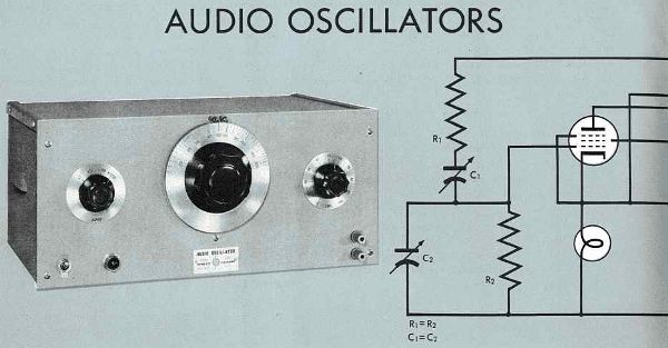
ADVANTAGES:
No zero setting • Great stability
Constant output
Wide frequency range
Logarithmic scale
Low distortion • Light weight
USE THEM FOR:
Amplifier testing
Broadcast transmitter audio response
Source of voltage for bridge measurements
Modulating signal generators
Supersonic voltage source
Driving mechanical systems
Synchronizing pulse generators
Loud speaker resonance tests
RESISTANCE-TUNED PRINCIPLE
There is a sound research story behind this revolutionary -hp- Resistance-tuned Audio Oscillator. Although audio-frequency oscillators have always been standard equipment throughout the communications and electronics fields, there were many "bugs" in types commonly available. These disadvantages included low stability, especially in the lower frequency ranges; need for constant resetting to insure accuracy; low portability, because of the essential weight and bulk of the instrument. So -hp- engineers set out to design and perfect an audio-frequency oscillator which would combine the high stability and very wide range of the coil-condenser type with the flexibility of operation of the beat frequency type. The result is the basically new Resistance-tuned Audio-frequency Oscillator, based on a new fundamental circuit and resulting in new speed and accuracy for electronic tests and measurements.
The fundamental resistance-tuned circuit of -hp- Audio Oscillators is shown above. The resonant frequency of this network is inversely proportional to the product of resistance and capacity. Thus the change in resonant frequency of this circuit is three times as great as that of the coil and condenser circuit. A ten to one frequency change is easily possible with the resistance-tuned circuit.
The resistance-capacity (frequency determining) network is operated in conjunction with a stabilized amplifier. Positive feedback is applied to this amplifier through the resistance-tuned network, resulting in a very high effective Q for the circuit. See figure 1. Negative feedback is also used, and operates in conjunction with a non-linear resistor to limit amplitude and decrease distortion. It also helps in providing a constant and extremely stable output over the entire range. See figure 2.
NO ZERO SETTING
The excellent physical layout of -hp- Audio Oscillators has much to do with their satisfactory performance. Thermal drift is kept at a minimum by proper placement of components, and by means of low temperature coefficient elements in the resistance network. Furthermore, this thermal drift is not magnified, as is the case with the beat frequency type oscillator. Thus calibration is accurate under all operating conditions, without the inconvenience of constant zero setting, even within the first few minutes of operation. The constant output of these oscillators makes it easy to check the frequency response of the apparatus quickly, easily, accurately.
ONLY THREE DIALS
There are only three controls on the panel. They are the main frequency dial which covers a frequency range of 10 to 1; a range switch which selects the desired frequency band, and an amplitude control to vary the output signal level.
USES
The primary function of an audio-frequency oscillator is to generate an accurately controlled signal of known frequency. This signal may be used to check the performance of audio amplifiers, broadcast transmitters, and similar equipment. Although applications in the related fields of electronics are of first importance, the usefulness of the -hp- Resistance-tuned Audio Oscillator is by no means limited to the electrical engineering fields. They may be used, for example, to drive mechanical systems, in order to measure resonance and stability. Other measurements of mechanical equipment include measurements of the output frequency of rotating equipment, such as generators and dynamotors.
-hp- Resistance-tuned Audio Oscillators provide an excellent source of voltage for accurate bridge measurements. The output is sufficient to drive signal generators and other equipment requiring considerable power. Certain models ate also adapted to work in the supersonic range.
The usefulness of these oscillators is greatly increased because they are small and light in weight; thus easy to carry around. In short, the speed and accuracy of -hp- Resistance-tuned Audio Oscillators make them ideal for an almost endless number of exacting jobs.
SPECIFICATIONS
Six standard models are available. The Models 200A and 200B have a transformer-coupled output amplifier which will deliver 1 watt into a matched load and are principally designed for use in audio testing. The Models 200C and 200D have a resistance-coupled output amplifier to provide uniform output voltage over their wide frequency range; they are principally useful when handling a wide range of frequencies, where a smaller amount of power is sufficient. Model 202D is a modification of Model 200D, with the frequency range extended down to 2 cycles per second. It is particularly useful where it is necessary to generate an extremely wide range and where low frequencies are involved, as in mechanical vibration problems. The Model 200I is an oscillator of the band spread type. It is intended for interpolation work and for applications where it is necessary that the frequency of oscillation be known very accurately. These oscillators are supplied in a relay rack mounting, as the 200AR, 200BR, 200CR, 200DR, 202DR, and 200IR.
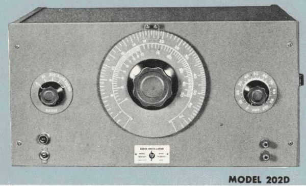
Frequency Range:
Model 200A 35 cps to 35 kc
Model 200B 20 cps to 20 kc
Model 200C 20 cps to 200 kc
Model 200D 7 cps to 70 kc
Model 202D 2 cps to 70 kc
Model 200 I 6 cps to 6 kc
Calibration:
The dial is calibrated directly in cycles for the lowest range. A switch selects the range and indicates the proper multiplying factor. The dial calibration of Models 200A, 200B, and 200C covers approximately 180 degrees, with an equivalent scale length of 20 to 30 inches. Models 200D and 202D have dial calibrations covering approximately 300 degrees with a scale length of about 60 inches. Model 200 I is calibrated over approximately 300 degrees, and has a scale length of approximately 90 inches.
| 200A | 200B | |
| Range 1 | 35 - 350 cps | 20 - 200 cps |
| Range 2 | 350 - 3500 cps | 200 - 2000 cps |
| Range 3 | 3.5kc - 35 kc | 2 kc - 20 kc |
| 200C | 200D | |
| Range 1 | 20 - 200 cps | 7 - 70 cps |
| Range 2 | 200 - 2000 cps | 70 - 700 cps |
| Range 3 | 2 kc - 20 kc | 700 cps - 7000 cps |
| Range 4 | 20 kc - 200 kc | 7 kc - 70 kc |
| 200I | ||
| A x1 | 6 - 20 cps | |
| B x1 | 20 - 60 cps | |
| A x10 | 60 - 200 cps | |
| B x10 | 200 - 600 cps | |
| A x100 | 600 - 2000 cps | |
| B x100 | 2 kc - 6 kc |
Stability:
Under normal conditions the frequency drift is less than ±2% even including initial warm-ups. Plus or minus 20% line voltage variations change the frequency less than ±0.2%, at 1 kc. No zero setting is necessary on these oscillators.
On Model 200I, if the ranges are standardized against a suitable frequency standard from time to time, accuracy better than 1% can be maintained.
Output:
The Models 200A and 200B will supply one watt or 22.5 volts output into a matched resistance load of 500 ohms, and 25 volts on open circuit.
Models 200C, 200D, 202D, and 200I will deliver 100 milliwatts or 10 volts into a 1000 ohm load. The internal impedance of the output amplifier is about 50 ohms at 1000 cps.
Frequency Response
The output voltages of Models 200A and 200B are constant within plus or minus one decibel from 20 cps to 15 kc.
The output voltage of the Model 200C is constant within plus or minus one decibel from 20 cps to 150 kc.
The output voltages of the Models 200D and 202D are constant within plus or minus one decibel from 7 cps to 70 kc.
The Model 202D will be within plus or minus 2 decibels from 2 cps to 7 cps.
The frequency response of the 200I is plus or minus one decibel from 6 cps to 6,000 cps.
Distortion:
The total rms distortion contained in the waveform of the various models is within the following limits:
Models 200A and 200B, less than 1% distortion from 35 cps to 20 kc.
Model 200C, less than 1% distortion from 20 cps to 20 kc.
Model 200D, less than 1%; distortion from 10 cps to 20 kc.
Model 202D, less than 1% at rated output voltage from 10 cps to 70 kc.
Model 200I, distortion less than 1 % above 10 cps, and only slightly more than this at lower frequencies.
Hum Voltage: the hum voltage is less than 0.1% of maximum output voltages.
Power Supply: 115 volts, 50/60 cycles, 50 watts.
Mounting:
The cabinet models are mounted in an attractive steel cabinet finished in wrinkle gray.
The relay rack mounting fits the standard 19" relay rack with ¾" spacing. The dust cover mounts on the chassis and is removable from the rear.
| Model | Mounting | Length | Height | Depth | Weight |
|---|---|---|---|---|---|
| 200A | Cabinet | 16" | 8" | 9" | 32 lbs |
| 200B | Cabinet | 16" | 8" | 9" | 32 lbs |
| 200C | Cabinet | 16" | 8" | 9" | 30 lbs |
| 200D | Cabinet | 17" | 8¾" | 11" | 32 lbs |
| 200 I | Cabinet | 17" | 8½" | 10¾" | 32 lbs |
| 200AR | Relay Rack | 19" | 8½" | 9" | 35 lbs |
| 200BR | Relay Rack | 19" | 7" | 9" | 35 lbs |
| 200CR | Relay Rack | 19" | 7" | 9" | 35 lbs |
| 200DR | Relay Rack | 19" | 8¾" | 11" | 37 lbs |
| 202DR | Relay Rack | 19" | 8¾" | 11" | 37 lbs |
| 200IR | Relay Rack | 19" | 8¾" | 11" | 37 lbs |
Average shipping weight 42 lbs.
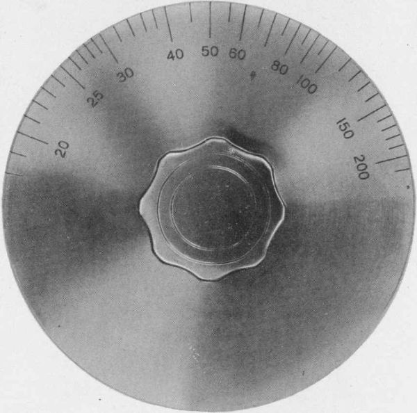
200B AND 200C
Here is the main tuning dial of -hp- Models 200B and 200C Audio Oscillators. Range is 20 cps to 20 kc on 200B, with dial calibrated over approximately 180° and effective scale length of about 20"; 200C has range of 20 cps to 200 kc and effective scale length of about 26".
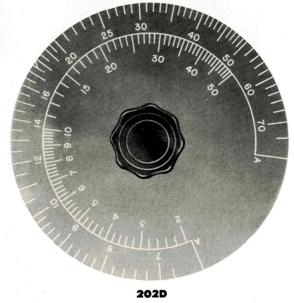
The -hp- Model 202D is a modification of the 200D, which extends the range down to 2 cps. The tuning dial is calibrated over approximately 300°; the effective scale length is about 75". Before calibration, all -hp- Audio Oscillators are operated for a long period so as to be completely stabilized.
.jpg)
Main tuning dial of -hp- Model 200D is calibrated over approximately 300° and has an effective scale length of about 60". This wide range instrument (from 7 cps to 70 kc) owes much of its speed and accuracy of operation to the precisely calibrated and easily controlled tuning dial pictured above.

Main tuning dial of the 200I, which is an oscillator of the band-spread type, intended for comparison work. The dial is calibrated over approximately 300° with effective scale length about 90" and range of 6 cps to 6 kc. Each Model 200I is carefully hand calibrated to insure maximum accuracy.
Pius Steiner, 16.Sep.12

