Supra-Selector 37 SB4346GW
Körting-Radio; Leipzig, später Grassau
- Country
- Germany
- Manufacturer / Brand
- Körting-Radio; Leipzig, später Grassau
- Year
- 1936/1937
- Category
- Broadcast Receiver - or past WW2 Tuner
- Radiomuseum.org ID
- 2433
-
- alternative name: Dietz & Ritter GmbH, Dr.
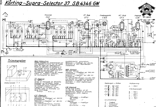
Click on the schematic thumbnail to request the schematic as a free document.
- Number of Tubes
- 6
- Main principle
- Superheterodyne (common); ZF/IF 468 kHz
- Tuned circuits
- 7 AM circuit(s)
- Wave bands
- Broadcast, Long Wave and 2 x Short Wave.
- Power type and voltage
- AC/DC-set / 110; 125; 150; 220; 240 Volt
- Loudspeaker
- Permanent Magnet Dynamic (PDyn) Loudspeaker (moving coil)
- Material
- Wooden case
- from Radiomuseum.org
- Model: Supra-Selector 37 SB4346GW - Körting-Radio; Leipzig, später
- Shape
- Tablemodel, low profile (big size).
- Dimensions (WHD)
- 490 x 404 x 305 mm / 19.3 x 15.9 x 12 inch
- Notes
- variable Bandbreite. Abstimmanzeige durch Glimmröhre. Spartransformator!!.
- Net weight (2.2 lb = 1 kg)
- 22 kg / 48 lb 7.3 oz (48.458 lb)
- Price in first year of sale
- 415.00 RM
- Source of data
- HandB.d.d.Rundfunk-Handels 1936/37 / Radiokatalog Band 1, Ernst Erb
- Circuit diagram reference
- Lange+Schenk+FS-Röhrenbestückung
- Other Models
-
Here you find 818 models, 671 with images and 471 with schematics for wireless sets etc. In French: TSF for Télégraphie sans fil.
All listed radios etc. from Körting-Radio; Leipzig, später Grassau
Collections
The model Supra-Selector 37 is part of the collections of the following members.
Forum contributions about this model: Körting-Radio;: Supra-Selector 37 SB4346GW
Threads: 1 | Posts: 4
I am having difficulty getting the 6 MHz coil slug adjusted for the K1 SW band. 12 MHz trimmer cap adjusts just fine. But the 6 MHz slug can be pulled out of the coil but the oscillator is still running too low. I have cleaned this coil of all dirt and contaminants.
Are theses coil forms or wire insulation subject to deterioration? I have disassembled and cleaned the Oscillator section and switches a few times. Insured there were no visible damages to the oscillator coil. I changed the oscillator 50 pf (was 62pf) grid capacitor and the G2 to cathode 500pf (was 637 pf) capacitor.
I even tried to align the SW at 12 MHz minus IF but the trimmers did not cover that range.
I am open to any suggestion.
Paul E. Pinyot † 2013, 10.May.12


