11-20Z (Issue 2)
Kriesler Radio Company; Newtown (Sydney)
- Country
- Australia
- Manufacturer / Brand
- Kriesler Radio Company; Newtown (Sydney)
- Year
- 1951
- Category
- Broadcast Receiver - or past WW2 Tuner
- Radiomuseum.org ID
- 230343
Click on the schematic thumbnail to request the schematic as a free document.
- Number of Tubes
- 4
- Main principle
- Superheterodyne (common); ZF/IF 455 kHz; 2 AF stage(s); Reflex
- Tuned circuits
- 6 AM circuit(s)
- Wave bands
- Broadcast and Short Wave (SW).
- Power type and voltage
- Alternating Current supply (AC) / 220; 240 Volt
- Loudspeaker
- Electro Magnetic Dynamic LS (moving-coil with field excitation coil) / Ø 5 inch = 12.7 cm
- Material
- Bakelite or Plastics (type unknown)
- from Radiomuseum.org
- Model: 11-20Z - Kriesler Radio Company;
- Shape
- Tablemodel without push buttons, Mantel/Midget/Compact up to 14
- Dimensions (WHD)
- 308 x 225 x 222 mm / 12.1 x 8.9 x 8.7 inch
- Notes
-
The 11-20 had 27 variants, differing in valve line up, speaker type, circuit variations etc.
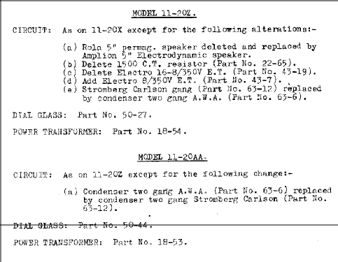
CIRCUIT: As on 11-20X except for the following changes:-
(a) Rola 5" permag. speaker deleted and replaced by Amplion 5" Electrodynamic speaker. (b) Delete 1500 C.T, resistor (Part No. 22-65). (c) Delete Electro 16-8/350v E.T. (Part No. 22-65). (d) Add Electro 8/350v E.T. (Part No. 43-7). (e) Stromberg Carlson gang (Part No. 63-12) replaced by condenser two gang A.W.A ( Part No. 63-6).
- Circuit diagram reference
- Australian Official Radio Service Manual Vol. IX
- Literature/Schematics (2)
- - - Manufacturers Literature (Kriesler Technical Service Instructions.)
- Author
- Model page created by Stuart Irwin. See "Data change" for further contributors.
- Other Models
-
Here you find 898 models, 445 with images and 436 with schematics for wireless sets etc. In French: TSF for Télégraphie sans fil.
All listed radios etc. from Kriesler Radio Company; Newtown (Sydney)

