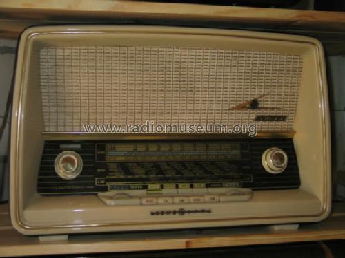
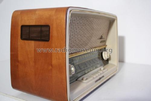
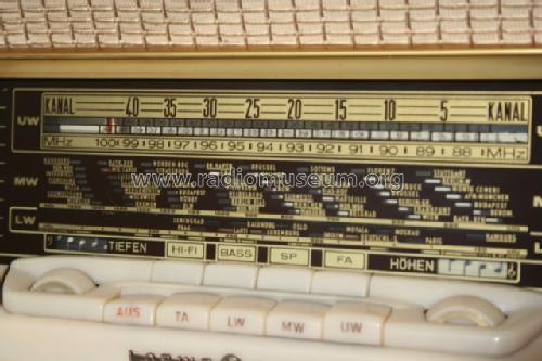
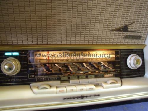
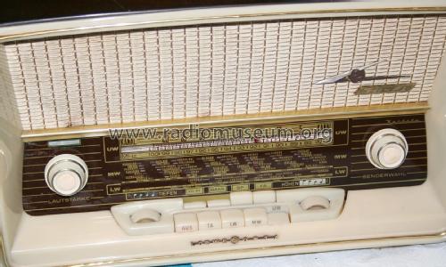
Kantate 3721W
Loewe-(Opta); Deutschland
- País
- Alemania
- Fabricante / Marca
- Loewe-(Opta); Deutschland
- Año
- 1958/1959
- Categoría
- Radio - o Sintonizador pasado WW2
- Radiomuseum.org ID
- 21711
-
- alternative name: Löwe Radio
Haga clic en la miniatura esquemática para solicitarlo como documento gratuito.
- Numero de valvulas
- 6
- Numero de transistores
- Semiconductores
- B250C75
- Principio principal
- Superheterodino en general; ZF/IF 460/10700 kHz
- Número de circuitos sintonía
- 6 Circuíto(s) AM 10 Circuíto(s) FM
- Gama de ondas
- OM, OL y FM
- Tensión de funcionamiento
- Red: Corriente alterna (CA, Inglés = AC) / 110; 127; 160; 220 Volt
- Altavoz
- 2 Altavoces
- Material
- Madera
- de Radiomuseum.org
- Modelo: Kantate 3721W - Loewe-Opta; Deutschland
- Forma
- Sobremesa de botonera.
- Ancho, altura, profundidad
- 490 x 310 x 250 mm / 19.3 x 12.2 x 9.8 inch
- Anotaciones
-
Ferrit-Antenne für MW und LW.
- Peso neto
- 8.5 kg / 18 lb 11.6 oz (18.722 lb)
- Precio durante el primer año
- 269.00 DM
- Ext. procedencia de los datos
- Erb
- Procedencia de los datos
- HdB d.Rdf-& Ferns-GrH 1958/59
- Documentación / Esquemas (1)
- -- Schematic
- Otros modelos
-
Donde encontrará 1645 modelos, 1382 con imágenes y 1188 con esquemas.
Ir al listado general de Loewe-(Opta); Deutschland
Colecciones
El modelo Kantate es parte de las colecciones de los siguientes miembros.
Contribuciones en el Foro acerca de este modelo: Loewe-Opta;: Kantate 3721W
Hilos: 2 | Mensajes: 4
Dear collegues,
I did a restoration work on a Loewe Opta Kantate 3721w radio which involved replacing the power transformer, taken from a Philips BCH462A radio, replacing the levelling capacitors and replacing the selenium rectifier with two diodes.
Due to these changes the anode voltage increased to about 305 V, also due to the higher mains voltage, now of about 240 Vac. To reduce this anode voltage I inserted a load resistor which reduced the voltage to about 260 V. In addition to these interventions on the power supply circuit, I had to replace the coupling capacitor between the EABC80 and the EL84 and on the latter I also replaced the capacitor and the cathode resistor: at this point the radio has reached a good level of operation.
That said, I come to the point for which I ask for your opinion.
Measuring all the voltages these are aligned with those indicated in the schematic, but I was surprised by the voltage I measured on the anode of the diode of the EABC80 pin2 which turns out to be about -46 V, with a good incoming signal, which frankly, in my little experience, I had never seen so high, so I ask if this represents a situation that can be considered normal or if instead it derives from some anomaly generated I don't know where and from what.
Thank you very much for the help you can give me.
Roberto
Roberto Licandro, 03.Sep.22
ich habe einen Kantate 3721, da läuft der UKW-Sender innerhalb der ersten 20 Minuten weg. D.h. der UKW-Oszillator (ECC85) ist nicht stabil. Er verändert seine Frequenz um 2 MHZ nach oben. Ich habe schon mehrere ECC85 ausprobiert, aber ohne Erfolg. Nach diesen 20 Minuten läuft er stabil und man muß nicht mehr nachstellen.
Bevor ich jetzt lange und zeitaufwändig such, dacht ich mir, fragst mal einen Fachmann ;-). Kennt jemand dieses Problem und weiß Abhilfe ?
Ich denke dass es nicht typspezifisch ist, sondern dass es bei anderen Herstellern das gleiche Problem geben könnte. Diese UKW-Empfangsteile mit der ECC85 waren ja bei vielen Radios dieser Zeit fast gleich.
Mit besten Dank im Voraus und vielen Grüßen
Andreas Sommerer
Andreas Sommerer, 14.Dec.05


