Radio Unit ADT
Lowther Manufacturing Co; Kent
- Produttore / Marca
- Lowther Manufacturing Co; Kent
- Anno
- 1936
- Categoria
- Radio (o sintonizzatore del dopoguerra WW2)
- Radiomuseum.org ID
- 340687
- Numero di tubi
- 5
- Principio generale
- Supereterodina e TRF (amplif. diretta); Principio di ricezione speciale (descrivere nelle note)
- Gamme d'onda
- Onde medie (OM) e onde lunghe (OL).
- Tensioni di funzionamento
- Fornita mediante altra unità o unità principale. / 4, 300 Volt
- Altoparlante
- - Per cuffie o amplificatori esterni
- Potenza d'uscita
- 5 W (qualità ignota)
- Materiali
- Mobile di metallo, valvole visibili
- Radiomuseum.org
- Modello: Radio Unit ADT - Lowther Manufacturing Co; Kent
- Forma
- Chassis o in scatola da montaggio
- Annotazioni
-
Radio Unit ATS
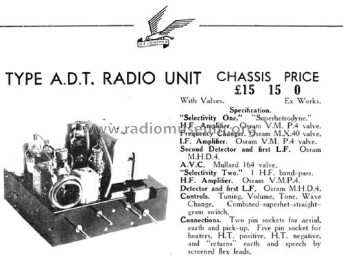
This dual-purpose radio unit functions both as a superheterodyne and as a straight "constant bandwidth" bandpass tuner, the former being position selectivity No. 1 and the latter selectivity No. 2 on the selection knob.
In position No.1 the aerial feeds a " constant bandwidth" band-pass coupling to a VMP4 acting as an HF amplifier followed by a tuned HF transformer coupling into the control grid of an MX40 as the first detector and oscillator of the conventional circuit, with arrangements so made as to keep the oscillator volts constant over the whole tuning range.In the anode of the valve are two IF transformers coupled direct, the peak separation of the four-tuned circuit being 8 kHz.
The last of these feeds the IF amplifier valve and also an HF Pentode in the anode which is a third IF transformer feeding both diodes of the second detector.The AVC valve is also fed from this transformer, the control is about 5 dB for a carrier intensity variation of approximately 90:1. The AVC line is very comprehensively filtered with various portions in each stage.
The amount of control is variable to suit prevailing conditions, "quiet" tuning can be fitted when desired.
The second detector circuit is conventional with IF and HF filters in diodes and anodes.
The volume control is the grid leak of the first valve on the amplifier chassis thus leaving any tone correction and pickup input circuit in the first portion unaffected.
A tuning meter in the anode circuit of the IF valve is part of the tuning scale which is calibrated with station names.
- Prezzo nel primo anno
- 15.75 GB £
- Bibliografia
- - - Manufacturers Literature (Lowther Voigt Radio, Season 1936-37, Page 14.)
- Autore
- Modello inviato da Gary Cowans. Utilizzare "Proponi modifica" per inviare ulteriori dati.
- Altri modelli
-
In questo link sono elencati 56 modelli, di cui 51 con immagini e 2 con schemi.
Elenco delle radio e altri apparecchi della Lowther Manufacturing Co; Kent