Inductuner
Mallory, P.R. & Co.; Indianapolis, IN
- País
- Estados Unidos
- Fabricante / Marca
- Mallory, P.R. & Co.; Indianapolis, IN
- Año
- 1951 ?
- Categoría
- Pieza de radio (no módulo)
- Radiomuseum.org ID
- 160980
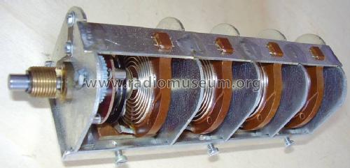
Internal view, right side.
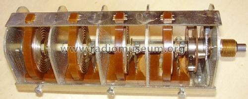
Internal view, left side.
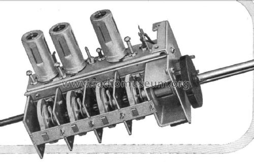
A Mallory TV tuner as advertised in 1951.
- Gama de ondas
- - no hay
- Tensión de funcionamiento
- No necesita alimentación
- de Radiomuseum.org
- Modelo: Inductuner - Mallory, P.R. & Co.;
- Anotaciones
- Inductuner was the registered mark for a multiple variable inductor. The unit was composed by two, three or four phenolic dishes each containing a spiral winding of three to six turns. A brush for each plate, driven by the common control shaft, follows the winding.
Inductuners were widely used in continuously tuned RF tuners, such as in TV applications. Continuous coverage from 50 to 220MHz was possible with such a device.
- Procedencia de los datos
- -- Original prospect or advert
- Documentación / Esquemas (1)
- Electronics, April 1951
- Autor
- Modelo creado por Emilio Ciardiello. Ver en "Modificar Ficha" los participantes posteriores.
- Otros modelos
-
Donde encontrará 39 modelos, 32 con imágenes y 2 con esquemas.
Ir al listado general de Mallory, P.R. & Co.; Indianapolis, IN
Colecciones
El modelo Inductuner es parte de las colecciones de los siguientes miembros.
Contribuciones en el Foro acerca de este modelo: Mallory, P.R. & Co.;: Inductuner
Hilos: 1 | Mensajes: 3
Fellow Radiophiles,
Ghirardi and Johnson have instructions for aligment of DuMont's TV VHF "Inputuner" in their 1952 edition of "Radio and Television Receiver Troubleshooting and Repair".
The "Inputuner" VHF TV tuner design is based on the variable inductance Mallory-Ware "Inductuner".
The variable inductance is based on the principle of shorting out unused sections of of very high Q coil.
The advantage of shorting turns instead of simply moving a tap with the unused coil section left open is that the unused coil will probably have self resonance in the range where the low inductance section of the coil being used is operating.
The Variometer method that was popular in the 1920's, where two equal inductors are continuously varied in each other's field, such that at one orientation their fields reinforce for a net inductance that is nearly four times the inductance of the either coil, and 180° away they cancel and present a very small, but lossy inductance.
The Variometer method also suffers from poor Q at low inductance values.
Note how in the Inputuner, the trimmer coils are adjusted for the higher frequency end of the dial, and the trimmer capacitors are adjusted for the low frequency end of the dial. This is the usual procedure when variable inductors are used. The opposite procedure should be more familiar because most tuners use variable capacitors.
I scanned the short article about the Inductuner and Inputuner from page 512 chapter 14. I performed OCR to get text embedded text behind the scanned images. This text can be selected, searched, or copied for translation to other languages using Google-translate.
Regards,
-Joe
Joe Sousa, 12.May.10