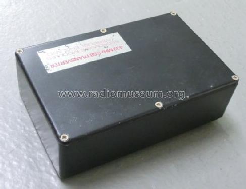
Linear-Transverter MMT 432/144
Microwave Modules Ltd.; Liverpool
- Country
- Great Britain (UK)
- Manufacturer / Brand
- Microwave Modules Ltd.; Liverpool
- Year
- 1978 ?
- Category
- Amateur Equipment (Other, but not Key)
- Radiomuseum.org ID
- 347339
- Number of Transistors
- Semiconductors present.
- Semiconductors
- Main principle
- RF Converter/Adapter (not voltage converter); ZF/IF 28000 kHz
- Wave bands
- Wave Bands given in the notes.
- Details
- Converter
- Power type and voltage
- Powered by external power supply or a main unit. / DC: 11 - 13.8 Volt
- Loudspeaker
- - - No sound reproduction output.
- Material
- Metal case
- from Radiomuseum.org
- Model: Linear-Transverter MMT 432/144 - Microwave Modules Ltd.;
- Shape
- Tablemodel, with any shape - general.
- Dimensions (WHD)
- 187 x 53 x 120 mm / 7.4 x 2.1 x 4.7 inch
- Notes
-
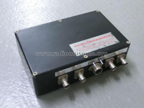
Microwave Modules Ltd. Linear-Transverter MMT 432/144. Frequency coverage 432 - 434 MHz and 434 - 436 MHz (433.6 - 435.6 MHz for UK model) in two ranges. Input frequency 144 - 146 MHz. Output 10 Watts RF max. HF-VOX built-in.
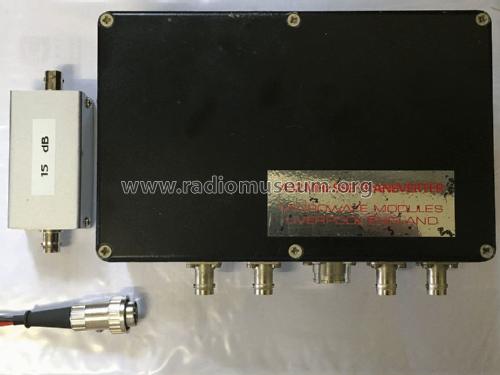
For operation with more than 0.5 Watts input (maximum 10 Watts) a separate 15 db input attenuator is mandatory!
Very early models had only one frequency range (432 - 434 MHz) and an inbuilt attenuator.
- Net weight (2.2 lb = 1 kg)
- 0.975 kg / 2 lb 2.4 oz (2.148 lb)
- Price in first year of sale
- 780.00 DM
- Mentioned in
- -- Original-techn. papers. (Manual)
- Author
- Model page created by a member from D. See "Data change" for further contributors.
- Other Models
-
Here you find 16 models, 15 with images and 5 with schematics for wireless sets etc. In French: TSF for Télégraphie sans fil.
All listed radios etc. from Microwave Modules Ltd.; Liverpool
Collections
The model Linear-Transverter is part of the collections of the following members.
Forum contributions about this model: Microwave Modules: Linear-Transverter MMT 432/144
Threads: 2 | Posts: 3
For an upcoming HAM radio project I was looking for a 2m/70cm transverter. The coincidental Ebay offer of a Microwave Modules MMT432/144 came just in time. The transverter was offered without further explanation as defective and without accessories or documents. Also the external 15 dB attenuator was not included. The relatively low purchase price in connection with the rarity of this model let me then buy it despite a certain risk to acquire a dead piece that could not be reanimated with reasonable effort.
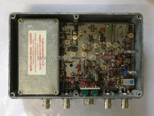
First of all it has to be said that the installation of the transverter's main board in the Eddystone die cast aluminium box is extremely maintenance and repair inconvenient: The power amp module, the subboard of the frequency switch and all connections have to be removed or desoldered beforehand, just to get to their rear solder side. I wanted to spare myself this effort.
The initial investigation revealed a solid short circuit in the power distribution. The transverter has in the input beside a reverse polarity protection also an additional overvoltage protection, which responds above 15 volts and is realized with a thyristor of the type MCR106-1. After detailed consideration and study of the circuit diagrams available in the internet I suspected this thyristor as the culprit: Possibly it had a solid conductivity in the PN junction due to a previously suffered considerable overvoltage, which would be quite possible during operation without additional fuse in the power supply line. No other components on the board could be made out in this regard. The reverse polarity protection diode was flawless.
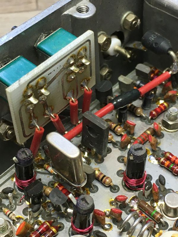
The replacement of the thyristor - the old one was cut off at its legs above the PCB and then the new one was soldered to it - did not change the initial situation. Very annoying, because now the main board had to be removed with a lot of effort to find the cause.
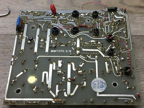
Underneath the circuit board a 22-µF/16-volt tantalum bead was found, which was responsible for the short circuit in the supply circuit! This surprise - and my extreme annoyance about this sneaky installation - the manufacturers of the transverter had definitely succeeded.
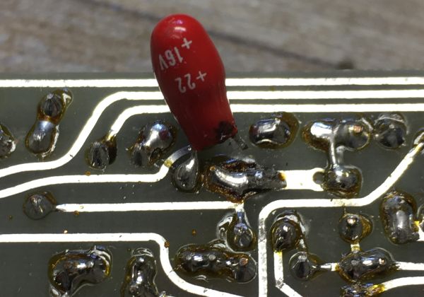
Replacing this tantalum capacitor with a conventional electrolytic of higher voltage capability eliminated the fault. Also the second tatalum of the same type and value above the circuit board was exchanged preventively. After laborious reassembly and subsequent realignment, this transverter, which is now over 45 years old, is now working properly again.
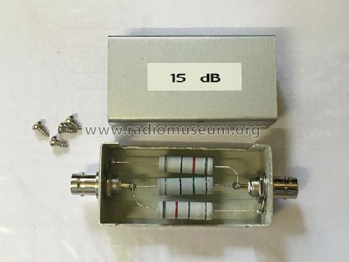
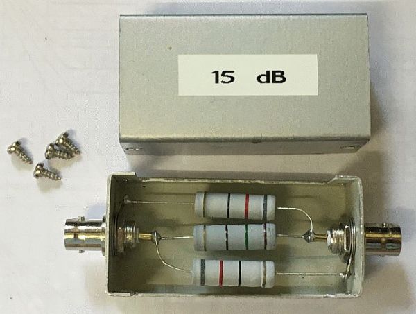
The 15 dB attenuator was realized with one 150 ohm resistor and two 82 ohm resistors - all three non-inductive five watt types - in a small Teko project box as PI circuit. This attenuator in front of the input of the transverter is mandatory for drive levels above 500 mW.
Conclusion: It is not always easy to reach the goal. Always count on constructive inadequacies or inaccessibility! After such a long time, tantalum electrolytic capacitors always harbor a certain susceptibility to failure and also a safety risk, especially if the voltage rating is low. In the case of damage they tend to a solid short circuit, which possibly causes further damage in the respective circuit. For this reason, it is also imperative to provide a separate fuse in the power supply connection line for devices that do not have an internal fuse, as in this case. If this is missing, catastrophic failures can occur. For the MMT-432/144 and similar devices a 2.5 A fast blow fuse is sufficient.
Eilert Menke, 17.Jun.23
Für ein angehendes AFu-Projekt war ich auf der Suche nach einem 2m/70cm-Transverter. Da kam das zufällige EBAY-Angebot eines Microwave Modules MMT432/144 gerade recht. Das Gerät wurde ohne weitere Erläuterung ausdrücklich als defekt und ohne weiteres Zubehör oder Unterlagen angeboten. Auch das externe 15-dB-Dämfungsglied war nicht dabei. Der relativ niedrige Kaufpreis in Verbindung mit der Seltenheit dieses Modell ließ mich dann trotz eines gewissen Risikos, eine mit vertretbarem Aufwand nicht wiederzubelebende Leiche zu erwerben, zugreifen.
Vorab ist zu sagen, daß der Gehäuseeinbau der Hauptplatine des Transverters extrem wartungs- bzw. reparaturunfreundlich gestaltet ist: So sind zuvor das Endstufenmodul, die Subplatine der Frequenzumschaltung und sämtliche Anschlüsse auszubauen bzw. abzulöten, nur um an deren rückseitiger Lötseite heranzukommen. Diesen Aufwand wollte ich mir möglichst ersparen.
Die Eingangsuntersuchung ergab einen soliden Kurzschluß in der Spannungsversorgung. Der Transverter hat im Eingang neben einem Verpolungsschutz auch einen zusätzlichen Überspannungsschutz, der oberhalb 15 Volt anspricht und mit einem Thyristor des Typs MCR106-1 realisiert wird. Nach eingehender Überlegung und Studium der im I-Netz verfügbaren Schaltpläne hatte ich diesen Thyristor als Übeltäter in Verdacht: Womöglich hatte er aufgrund einer zuvor erlittenen erheblichen Überspannung einen soliden Durchgang im PN-Übergang, was bei Betrieb ohne zusätzliche Absicherung in der Stromversorgungszuleitung durchaus möglich wäre. Andere Bauelemente auf der Platine waren in dieser Hinsicht nicht auszumachen. Die Verpolungsschutzdiode war einwandfrei.

Der Austausch des Thyristors (Bildmitte) - der alte wurde an seinen Beinen oberhalb der Platine abgeschnitten und dann der neue daran gelötet - brachte jedoch keine Veränderung der Ausgangssituation. Sehr ärgerlich, denn nun mußte zur weiteren Ursachenforschung doch noch mit viel Aufwand die Hauptplatine ausgebaut werden.

Unterhalb der Platine kam eine 22-µF/16-Volt-Tantalperle zum Vorschein, die den Kurzschluß in der Versorgungsschaltung zu verantworten hatte! Diese Überraschung - und meine extreme Verärgerung über diese hinterhältige Installation - war den Produzenten des Gerätes auf jeden Fall gelungen.

Der Austausch dieses Tantalelkos gegen einen herkömmlichen Elektrolyten höherer Spannungsfestigkeit beseitigte den Fehler. Auch der zweite, bauart- und wertgleiche Tantalelko oberhalb der Platine wurde präventiv getauscht. Nach mühsamem Zusammenbau und anschließendem Neuabgleich funktioniert dieser inzwischen über 45 Jahre alte Transverter wieder einwandfrei.
Das 15-dB-Dämpfungsglied wurde mit einem 150-Ohm-Widerstand und zwei 82-Ohm-Widerständen - alle drei nichtinduktive Fünf-Watt-Typen - in einer kleinen Teko-Box als PI-Schaltung realisiert. Dieses Dämpfungsglied vor dem Eingang des Transverters ist bei Ansteuerleistungen größer 500 mW zwingend erforderlich.

Conclusio: Man kommt nicht immer einfach zum Ziel. Rechne stets mit konstruktiven Unzulänglich- bzw. Unzugänglichkeiten! Tantalelkos bergen nach so langer Zeit immer eine gewisse Fehleranfälligkeit und auch ein Sicherheitsrisiko, insbesondere bei knapp bemessener Spannungsfestigkeit. Im Schadenfall neigen sie durch Feldkristallisation zu einem soliden Kurzschluß, der womöglich weitere Schäden in der jeweiligen Schaltung nach sich zieht. Deshalb ist es auch zwingend nötig, bei Geräten, die wie hier keine interne Sicherung haben, in der Anschlußleitung der Stromversorgung eine separate Absicherung vorzunehmen. Fehlt diese, kann es zu katastrophalen Ausfällen kommen. Beim MMT-432/144 und ähnlichen Geräten ist eine flinke 2,5-A-Feinscherung ausreichend.
Eilert Menke, 16.Jun.23
