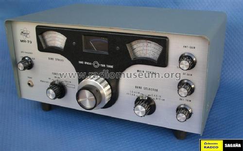
Allwellen-Empfänger MR-73
Minix, Hannover
- País
- Alemania
- Fabricante / Marca
- Minix, Hannover
- Año
- 1973–1976 ?
- Categoría
- Receptor para radioaficionados (puede incluir bandas de radiodifusión publ.)
- Radiomuseum.org ID
- 90249
-
- Brand: Richter & Co; Hannover
Haga clic en la miniatura esquemática para solicitarlo como documento gratuito.
- Numero de transistores
- 13
- Principio principal
- Superheterodino con paso previo de RF; ZF/IF 455 kHz
- Gama de ondas
- OM y más de dos OC
- Tensión de funcionamiento
- Line plus power jack, mostly with battery or storage battery / 120; 220 / 12 Volt
- Altavoz
- Altavoz dinámico (de imán permanente)
- Material
- Metálico
- de Radiomuseum.org
- Modelo: Allwellen-Empfänger MR-73 - Minix, Hannover
- Forma
- Sobremesa de cualquier forma, detalles no conocidos.
- Ancho, altura, profundidad
- 360 x 160 x 220 mm / 14.2 x 6.3 x 8.7 inch
- Anotaciones
-
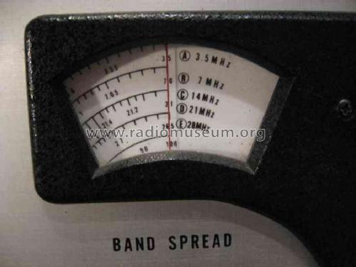
Minix MR-73. Frequenzbereich 550 kHz bis 30,0 MHz in vier Bereichen, Bandspreizung für Amateurbänder 80, 40, 20, 15 und 10 m. Betriebsarten AM, CW/SSB mit BFO; keramisches ZF-Filter; Störbegrenzer. Betrieb mit externer 12-V-Gleichspannungsquelle möglich. Entwicklung und Vertrieb durch Richter & Co. in Hannover, hergestellt in Japan. Vorgänger des MR-73B.
Halbleiter oben nur einmal pro Typ gelistet.
- Peso neto
- 6.5 kg / 14 lb 5.1 oz (14.317 lb)
- Precio durante el primer año
- 560.00 DM
- Mencionado en
- (D) Kurzbennennung in Hobby Nr. 11, 19.5.1976, S. 112
- Documentación / Esquemas (1)
- Katalog 1974 der Fa. Richter & Co.; Hannover
- Autor
- Modelo creado por Martin Bösch. Ver en "Modificar Ficha" los participantes posteriores.
- Otros modelos
-
Donde encontrará 46 modelos, 41 con imágenes y 20 con esquemas.
Ir al listado general de Minix, Hannover
Colecciones
El modelo Allwellen-Empfänger es parte de las colecciones de los siguientes miembros.
Contribuciones en el Foro acerca de este modelo: Minix, Hannover: Allwellen-Empfänger MR-73
Hilos: 1 | Mensajes: 2
Bei den Transistoren für die Spannungsstabilisierung Tr.9 und Tr.10 sind im Schaltplan offensichtlich Kollektor und Emitter falsch gezeichnet (vertauscht).
Dietrich Grötzer, 30.Nov.10


