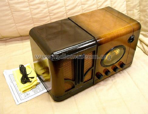
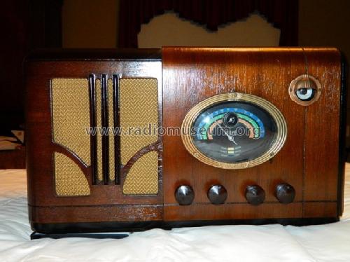
Airline 62-317 Ch= Belmont 787 Series A
Montgomery Ward & Co. (Wards, Airline); Chicago, IL
- Land
- USA
- Hersteller / Marke
- Montgomery Ward & Co. (Wards, Airline); Chicago, IL
- Jahr
- 1936/1937
- Kategorie
- Rundfunkempfänger (Radio - oder Tuner nach WW2)
- Radiomuseum.org ID
- 47997
-
- Marke: Airline or Air-Line
Klicken Sie auf den Schaltplanausschnitt, um diesen kostenlos als Dokument anzufordern.
- Anzahl Röhren
- 7
- Hauptprinzip
- Superhet allgemein; ZF/IF 465 kHz; 2 NF-Stufe(n)
- Anzahl Kreise
- 7 Kreis(e) AM
- Wellenbereiche
- Mittelwelle, Kurzwelle und Tropenband.
- Betriebsart / Volt
- Wechselstromspeisung / Either Transformer 50 to 60Hz: 105 to 115V or with taps at 108, 125, 150, 220, 250 Volt
- Lautsprecher
- Dynamischer LS, mit Erregerspule (elektrodynamisch) / Ø 6 inch = 15.2 cm
- Material
- Gerät mit Holzgehäuse
- von Radiomuseum.org
- Modell: Airline 62-317 Ch= Belmont 787 Series A - Montgomery Ward & Co. Wards,
- Form
- Tischgerät-gross, - Querformat (breiter als hoch oder quadratisch).
- Abmessungen (BHT)
- 17.5 x 10 x 8 inch / 445 x 254 x 203 mm
- Bemerkung
-
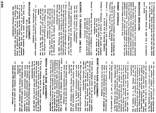
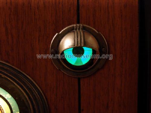
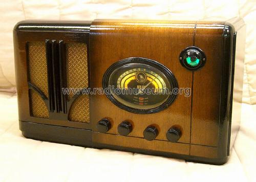
The Airline 62-317 is an AC operated 7 tube BC, Police and SW band receiver. Has tuning eye and band filter input circuit for BC band. The Airline model 62-317X is similar to this model except uses a 25Hz power transformer. Cabinet is two-toned wood.
Band Frequency Ranges are as follows:
BC Band (Blue Band)................535 - 1720kHz
Police Band (Green Band).........1.695 - 5.5MHz
SW Band (Buff Band)...............5.2 - 18.3MHzThe same schematic and chassis for this model is also used for models 62-317X, 62-249 and 62-249X.
This model was built for Montgomery Ward by the Belmont Radio Corp (B.R.C.), Chicago, ILL and uses same chassis as Belmont 787.
- Datenherkunft extern
- Ernst Erb
- Literaturnachweis
- Machine Age to Jet Age III
- Literatur/Schema (1)
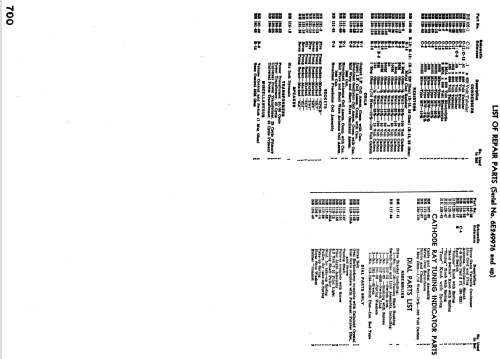
- Rider's Perpetual, Volume 14 = covering up to late 1942 (C=1944) (Pages 14-53, 14-54 14-124)
- Literatur/Schema (2)
- Airline Radio Service Manuals 1929-42 Volume I (Pages 697 to 700)
- Weitere Modelle
-
Hier finden Sie 2294 Modelle, davon 1462 mit Bildern und 1791 mit Schaltbildern.
Alle gelisteten Radios usw. von Montgomery Ward & Co. (Wards, Airline); Chicago, IL
Sammlungen
Das Modell Airline 62-317 befindet sich in den Sammlungen folgender Mitglieder.
Forumsbeiträge zum Modell: Montgomery Ward & Co: Airline 62-317 Ch= Belmont 787 Series A
Threads: 1 | Posts: 5
I have taken classes in electronics and barely missed getting my 2nd class FCC license but that was in the early 1970s.
I'm trying to remember as much as possible and sometimes the explanations given here are a bit too technical for me to understand completely.
This radio, by my understanding, has 7 tuned circuits in the broadcast band with 3 in the tuning gang, two in the IF stage and 4 more in between the stages. Am I close?
Robin
Robin Roeckers, 05.Feb.09


