- Country
- United States of America (USA)
- Manufacturer / Brand
- Montgomery Ward & Co. (Wards, Airline); Chicago, IL
- Year
- 1937
- Category
- Broadcast Receiver - or past WW2 Tuner
- Radiomuseum.org ID
- 48047
-
- Brand: Airline or Air-Line
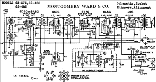
Click on the schematic thumbnail to request the schematic as a free document.
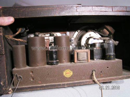
- Number of Tubes
- 6
- Main principle
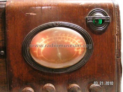
- Superheterodyne (common); ZF/IF 465 kHz; 3 AF stage(s)
- Tuned circuits
- 6 AM circuit(s)
- Wave bands
- Broadcast and Short Wave (SW).
- Power type and voltage
- Storage Battery for all (e.g. for car radios and amateur radios) / 6 Volt
- Loudspeaker
- Permanent Magnet Dynamic (PDyn) Loudspeaker (moving coil) / Ø 6 inch = 15.2 cm
- Material
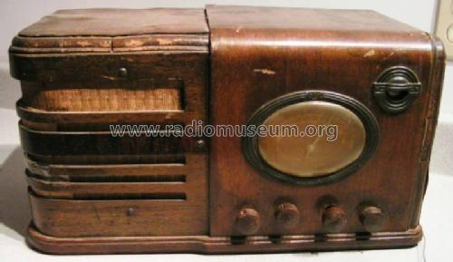
- Wooden case
- from Radiomuseum.org
- Model: 62-376 - Montgomery Ward & Co. Wards,
- Shape
- Tablemodel, with any shape - general.
- Notes
- Push-pull audio amplifier. Built-in vibrator for B+
- External source of data
- Ernst Erb
- Source of data
- Collector's Guide to Antique Radios 4. Edition
- Circuit diagram reference
- Rider's Perpetual, Volume 11 = ca. 1940 and before
- Mentioned in
- Rider's 11-14
- Other Models
-
Here you find 2294 models, 1462 with images and 1791 with schematics for wireless sets etc. In French: TSF for Télégraphie sans fil.
All listed radios etc. from Montgomery Ward & Co. (Wards, Airline); Chicago, IL
Forum contributions about this model: Montgomery Ward & Co: 62-376
Threads: 1 | Posts: 3
I have done several simple radio restorations and have little knowledge about circuitry. I picked up the referenced 6 volt Monkey Wards circa 1936 farm radio radio recently and am completely stumped about the Rider schematic as shown. I have read a bit about the farm radios and how they use vibrators to simulate AC current so that a transformer can be used to adjust the voltage. I have also read a number of articles about building a battery eliminator to bypass the vibrator and power the radio. So here are my questions:
-1- The schematic doesn't give voltages on the tube pins, but I assume all the "A" heater voltage on the tubes is 6 volts; however when it comes to the "B" voltage I am lost. It appears that the oscillator and IF amp tubes use 90 volts, but can't figure out the other three tubes. I also see 135 and 145 volt power in places.
-2- Will it be possible to build a battery eliminator for this radio? If so I obviously need help so any suggestions will be appreciated.
-3- The other thing that confuses me is that I don't see a rectifier anywhere? Is this because the vibrator only creates a pseudo AC power that can be processed by the transformer but is still actually DC power?
Arnie Anderson, 05.Apr.15