Airline 94BR3004
Montgomery Ward & Co. (Wards, Airline); Chicago, IL
- Produttore / Marca
- Montgomery Ward & Co. (Wards, Airline); Chicago, IL
- Anno
- 1949 ?
- Categoria
- Televisore (TV) / Monitor
- Radiomuseum.org ID
- 253888
-
- Brand: Airline or Air-Line
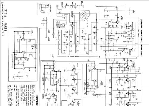
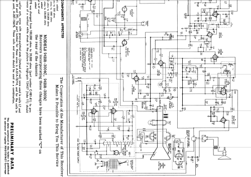
Clicca sulla miniatura dello schema per richiederlo come documento gratuito.
- Numero di tubi
- 25
- Valvole
- 6BH6 6J6 12AU6 12AU6 12AU6 12AU6 12AL5 12AU6 19T8 50L6GT 12AU7 12SN7 12AU6 50B5 50B5 50B5 35Z5GT 35Z5GT 12AU6 12SN7 50L6GT 35L6GT 35L6GT 1B3GT or 8016 10BP4 or 10FP4
- Principio generale
- Supereterodina con stadio RF; 2 Stadi BF
- Gamme d'onda
- Gamme d'onda nelle note.
- Tensioni di funzionamento
- Varie, dettagli nelle note o non conosciuti
- Altoparlante
- AP magnetodinamico (magnete permanente e bobina mobile)
- Radiomuseum.org
- Modello: Airline 94BR3004 - Montgomery Ward & Co. Wards,
- Annotazioni
-
The Airline 94BR-3004 is a b/w TV with US FCC standard VHF tuner channels 2 thru 13.
Model Airline 94BR-3004C:
Receivers incorporating the following changes have been marked "C" on the rear of the chassis. Components affected in Stages HOR. M.V. (Tubes 11A and 12A) and HORZ. AMP. (Tube 12A) are:
- L41, oscillator coil added
- R59 from 180 ohms to 330 ohms
- R60 from 33000 ohms to 1800 on
- R64 from 120000ohms to 330000 ohms
- R67 from 33000 ohms to 220000 on
- C86 (3300 mmf) added
- C92 from 82 mmf to 47 mmf
- C106 (150 mmf) added
- Resistor R95 was changed from 100000 ohms to 39000 ohms to prevent the occurrence of a vertical white streak in the picture if a high-gain 12AU/ (tub1 11) should be used.
On some earlier sets, cores with green painted ends (instead of red) were used in coils L7 and L9. The part number of these cores is A-51A-15714, and for the coils in which they are used, A-201-15675. These coils and cores should be used as a combination.
Switching arrangements for on-off switch:
- switch on volume control
- mercury switch
- or both in series
Plug-in sub-assembly for A-C operation
Plug-in sub-assembly for D-C operation (optional)
- Letteratura / Schemi (1)
- Photofact Folder, Howard W. SAMS (Set 91A Folder 3 1950)
- Autore
- Modello inviato da Geert Schulte. Utilizzare "Proponi modifica" per inviare ulteriori dati.
- Altri modelli
-
In questo link sono elencati 2294 modelli, di cui 1462 con immagini e 1791 con schemi.
Elenco delle radio e altri apparecchi della Montgomery Ward & Co. (Wards, Airline); Chicago, IL

