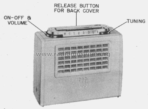
52L3 Ch= HS-327
Motorola Inc. (ex Galvin Mfg.Co. Chicago); Schaumburg (IL)
- Country
- United States of America (USA)
- Manufacturer / Brand
- Motorola Inc. (ex Galvin Mfg.Co. Chicago); Schaumburg (IL)
- Year
- 1951/1952
- Category
- Broadcast Receiver - or past WW2 Tuner
- Radiomuseum.org ID
- 48881
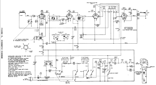
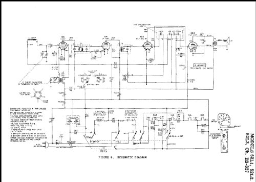
Click on the schematic thumbnail to request the schematic as a free document.
- Number of Tubes
- 4
- Number of Transistors
- Semiconductors
- Selenium-Rectifier
- Main principle
- Superheterodyne (common); ZF/IF 455 kHz; 2 AF stage(s)
- Tuned circuits
- 6 AM circuit(s)
- Wave bands
- Broadcast only (MW).
- Power type and voltage
- Line / Batteries (any type) / AC/DC 117 V / 2 x 1.5 (3V in series) & 67.5 Volt
- Loudspeaker
- Permanent Magnet Dynamic (PDyn) Loudspeaker (moving coil) / Ø 3.5 inch = 8.9 cm
- Material
- Plastics (no bakelite or catalin)
- from Radiomuseum.org
- Model: 52L3 Ch= HS-327 - Motorola Inc. ex Galvin Mfg.Co
- Shape
- Portable set > 8 inch (also usable without mains)
- Notes
-
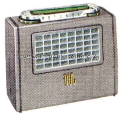
There are six models in this series. The later "A" models added a "B" Battery Saver slide switch, located in the upper right corner of the speaker grill. The two slide switch positions are: left (DISTANCE-HI), and right (LOCAL-LO). The DISTANCE-HI position increased the "B" battery drain and improved reception for long distance broadcasts. The original model "B" battery drain was fixed at the later "A" model DISTANCE-HI drain level.
Model Chassis Color Battery Saver Switch 52L1 HS-327 Green NO 52L2 HS-327 Maroon NO 52L3 HS-327 Gray NO 52L1A HS-357 Green YES 52L2A HS-357 Maroon YES 52L3A HS-357 Gray YES
- External source of data
- Ernst Erb
- Source of data
- The Radio Collector's Directory and Price Guide 1921 - 1965
- Circuit diagram reference
- Rider's Perpetual, Volume 23 (last), covering up to 1954
- Mentioned in
- Guide to Old Radios
- Literature/Schematics (3)
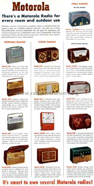
- Motorola Folder No. 3301 for 1952.
- Other Models
-
Here you find 4623 models, 2967 with images and 4122 with schematics for wireless sets etc. In French: TSF for Télégraphie sans fil.
All listed radios etc. from Motorola Inc. (ex Galvin Mfg.Co. Chicago); Schaumburg (IL)
