- Country
- Great Britain (UK)
- Manufacturer / Brand
- Murphy Radio Ltd.; Welwyn Garden City
- Year
- 1935
- Category
- Broadcast Receiver - or past WW2 Tuner
- Radiomuseum.org ID
- 130592
Click on the schematic thumbnail to request the schematic as a free document.
- Number of Tubes
- 9
- Main principle
- Superhet with RF-stage; ZF/IF 119 kHz
- Tuned circuits
- 8 AM circuit(s)
- Wave bands
- Broadcast (MW) and Long Wave.
- Power type and voltage
- Alternating Current supply (AC)
- Loudspeaker
- Electro Magnetic Dynamic LS (moving-coil with field excitation coil)
- Material
- Wooden case
- from Radiomuseum.org
- Model: A28C - Murphy Radio Ltd.; Welwyn
- Shape
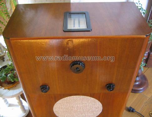
- Console, Lowboy (legs < 50 %).
- Notes
-
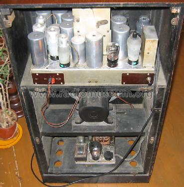
9-valve, AC-powered, superhet receiver with AFC and dynamic noise suppression.
The superheterodyne circuit comprises a signal-frequency HF amplifier, frequency changer, IF stage, double-diode rectifier and AVC valve, LF amplifier with tone correction and inter-station noise suppression, and a pentode output valve.
There are, in addition, two valves, whose special function is to correct reasonable errors of tuning on the part of the user. They are a double diode rectifier and a pentode valve arranged to shift slightly the tracking of the oscillator in the event of careless adjustment of the tuning control. There should be little excuse for inaccurate tuning, however, for the new tuning scale, let into the top of the cabinet, is of an improved type, quite free from parallax errors.
The medium and longwave pointers work in slots in the same plane as the scale, which, in addition to wavelength calibrations, now carries a selection of station names.
Wireless Word, August 30, 1935 Advertisement Page 259.
For the noise reduction description, see Forum Article.
The cabinet is finished in Indian Laurel and Walnut veneers.
- Source of data
- -- Collector info (Sammler)
- Mentioned in
- Wireless World (The), London (WW, 79) (August 30, 1935 Advertisement Page 259)
- Literature/Schematics (1)
- -- Schematic
- Literature/Schematics (2)
- - - Manufacturers Literature
- Author
- Model page created by Gottfried Silberhorn. See "Data change" for further contributors.
- Other Models
-
Here you find 367 models, 301 with images and 235 with schematics for wireless sets etc. In French: TSF for Télégraphie sans fil.
All listed radios etc. from Murphy Radio Ltd.; Welwyn Garden City
Forum contributions about this model: Murphy Radio Ltd.;: A28C
Threads: 1 | Posts: 1
Interstation Noise Suppression & the Murphy 28 Series
It is an unfortunate fact, from a radio engineering point of view, that the disturbances in the ether are not all caused by radio transmitting stations. Electrical discharges of all sorts (e.g., atmospherics, sparks from electric signs, motor commutators, etc.) contribute a very large proportion of the disturbances which can be detected by a radio receiver and give rise to the well-known extraneous noises emitted by the loudspeaker.
IMPORTANT DEFINITION.
Under some conditions, these noises can be quite terrifying to the less technically minded user, and I am sure that this fear is largely responsible for the limitation of the unskilled user's choice of stations. Even in less extreme cases, the disturbing and annoying effect of bursts of noise helps to make the user reluctant to take advantage of the available choice of programs. Some method of reducing or eliminating these distracting noises is therefore desirable and is met by a system known as Noise Suppression.
 This term is often misunderstood, for it is commonly believed that it refers to the removal of all unwanted noise whatsoever. This is not so, for at present no commercially practicable device is known that can be incorporated in a receiver in order to remove the background noise when listening to a program.
The term noise suppression-or, more correctly, inter-station noise suppression refers only to the elimination of the mush and interference experienced when tuning from one station to another, which is accentuated by the AVC action of increasing the sensitivity of the receiver between stations.
TYPES OF NOISE SUPPRESSION.
The ideal noise suppression system should be able to differentiate between undesirable noise and an acceptable program, and also should not be capable of introducing distortion. Let us examine the degree to which these two conditions are met by different forms of suppression circuit. Considering the first requirement, it is, of course, possible to differentiate between the noise and a signal which is stronger than the noise, merely by their relative intensities at the end of the high-frequency amplifier. This is the method often employed, and usually, the AVC system is tapped in some way to provide the necessary control of the noise suppression system as indicated in Fig. 1.
This arrangement, however, in general, suffers from two disadvantages; first, in order to ensure that bursts of noise are suppressed, it is necessary to make the suppression so drastic that programs of quite good entertainment value must be sacrificed. Secondly, a strong station will hold the suppression open for a considerable band on either side of the tune point, with the result that the effect of “sideband shriek” one of the most annoying forms of interstation noise will not be reduced. At night, when good stations are in close proximity on the dial, the effect may even be that the suppression will not come on at all over wide bands on the scale.
This disadvantage is avoided if the noise suppression is controlled by volts obtained from a highly selective circuit following the point from which AVC is taken, as shown in Fig. 2. As the set is detuned from a carrier, although the AVC keeps the signal constant at the audio detector, the response of the highly selective circuit decreases rapidly, and matters can be so arranged that the noise suppression comes into operation before the extreme sidebands are reached even on a strong station.
This type of noise suppression has also another advantage. Noise in general is spread over the whole range of wavelengths covered by the receiver, while the carrier of a station operates at only a single frequency. An extremely unselective receiver, therefore, will pick up a large amount of noise relative to the carrier, while on the other hand, a highly selective receiver will discriminate in favor of the wanted signal. Thus, by using a highly selective circuit to operate the noise suppression, the system may be adjusted so that the receiver remains suppressed in the face of a burst of high noise level, yet a relatively weak carrier is sufficient to sensitise the set.
It is apparent that this type of suppression circuit is greatly to be preferred, although it is, of course, more costly than the more common types. It has been employed in the design of the "28 " receivers, together with another special arrangement which avoids any possibility of distortion being introduced the second of the two desirable features of the " ideal " system mentioned earlier.
AVOIDING DISTORTION.
In most types of noise suppression, a valve in the IF chain (it may be a diode rectifier or an L.F. amplifier) is normally biased beyond the cut-off point, as shown at A in Fig. 3, so that the valve is paralysed. When a signal is received, a voltage is produced which partially removes this suppression bias to B and allows the valve to operate on its normal characteristics. If a weak signal is received, the initial bias may be removed just so far as to bring the operating point on or near the cut-off of the characteristic, as at C, and serious distortion will naturally result.
In the system used on the “28” receiver, the slope of the LF pentode valve is controlled not by moving the operating point to a different part of the characteristic (as happens when we alter the bias point of the control grid to which the signal is applied), but by changing the entire slope of the valve through bias variations on the outer grid.
The point is made clear in Fig. 4, whence it will be seen that the suppression operating point remains at the same potential, and therefore fixed in the centre of the characteristic, while the steepness of the slope is varied according to the strength of the signal controlling the outer grid bias, Thus distortion can never occur.
BACKGROUND NOISE A DIFFERENT PROBLEM.
I have explained the advantages of the noise suppression system used on the " 28 " series in reducing the noise between stations. The background noise obtained when actually listening to a program presents a very different problem, and in the case of the "28 " has been reduced to an attack on things completely external to the receiver itself notably the aerial. In a future article, I will discuss the methods which can be adopted to reduce this interference and increase the entertainment value obtained.
E. J. POWER CHIEF ENGINEER, Murphy Radio Ltd., Welwyn Garden City, Herts
Wireless Word, November 8, 1935 Advertisement Pages 2-3.
Gary Cowans, 03.Mar.22


