- Country
- Canada
- Manufacturer / Brand
- Northern Electric Co. Ltd.; Montreal, QC ; Belleville, ON
- Year
- 1925
- Category
- Broadcast Receiver - or past WW2 Tuner
- Radiomuseum.org ID
- 181198
Click on the schematic thumbnail to request the schematic as a free document.
- Number of Tubes
- 3
- Main principle
- TRF with regeneration; 2 AF stage(s)
- Tuned circuits
- 1 AM circuit(s)
- Wave bands
- Broadcast only (MW).
- Power type and voltage
- Storage and/or dry batteries
- Loudspeaker
- - This model requires external speaker(s).
- Material
- Wooden case
- from Radiomuseum.org
- Model: R24 - Northern Electric Co. Ltd.;
- Shape
- Tablemodel, Box - most often with Lid (NOT slant panel).
- Dimensions (WHD)
- 610 x 270 x 280 mm / 24 x 10.6 x 11 inch
- Notes
-
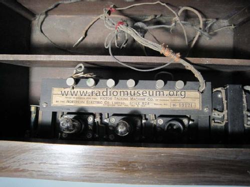
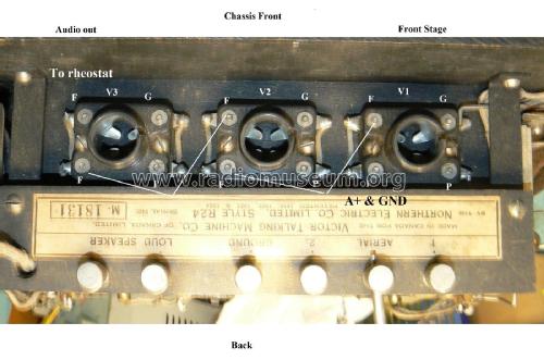
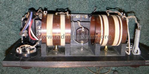
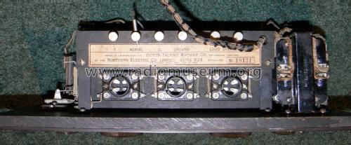
This model shows a sticker with the following text about brand and manufacturer: "Made in Canada for the Victor Talking Machine Co. of Canada Limited. By the Northern Electric Co. Limited. Style R24, Serial M-19121. Patented 1918, 1922, 1923 & 1924." There is no dash between R and 24. The tiny tubes R215A are made also by Northern Electric Co. Ltd. The cabinet is made of American Walnut. The model has Radiola III style coils. This is the first model of Northern Electric which does not display the tubes through holes in the front panel.
In the book "The early development of radio in Canada, 1901-1930", Robert P. Murray writes the following for that time:
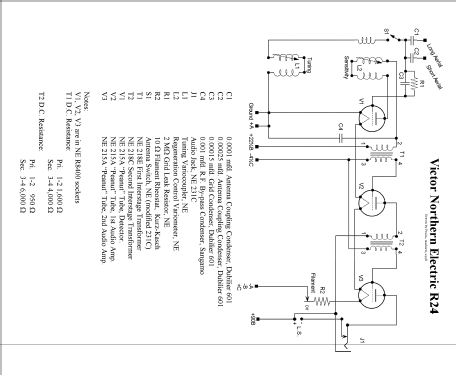
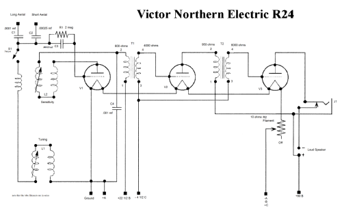
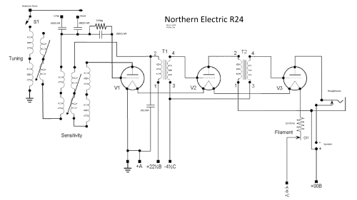
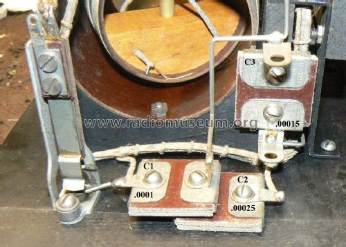
"On April 23, 1925, NE reached an agreement with the Victor Talking Machine Company of Canada Limited in Montreal. They began production of a series of receivers to which NE apparently contributed the chassis and Victor the cabinet. ... The first of these Victor/Northern electric models was the R-20 ... using two R-215-A tubes ... was much like the R-12." Then came R21 with three R215A tubes and R22 as R21 with a horizontal radio panel in a Victrola gramophone cabinet - and an upright Victrola was labeled type R23. Afte R24 followed in 1925 a type R30, a typical "three dialer" with 5 of the R2321DX tubes (functionally equal to UX201A). "After 1926, NE and Victor appear to have gone their separate ways." Victor made first its own receivers and then later presented models under the RCA Victor name.The schematic diagram by Paul Guiord simplifies the variometer and the connections. The tuning variometer has 4 coils and 4 terminals. The sensitivity variometer has 6 coils and 5 terninals. The antenna terminal has a jumper that is moved to either the short (1) or long (2) terminal for operation.
Many 215a tubes require applying Rocksett to the base due to aging of the original setting material. This prevents twisting off the glass envelope when seating in the socket.
- External source of data
- William Naftel, Halifax, Canada
- Mentioned in
- The Early Development of Radio in Canada 1901-1930 (Page 51 and Page 59)
- Author
- Model page created by Ernst Erb. See "Data change" for further contributors.
- Other Models
-
Here you find 291 models, 246 with images and 254 with schematics for wireless sets etc. In French: TSF for Télégraphie sans fil.
All listed radios etc. from Northern Electric Co. Ltd.; Montreal, QC ; Belleville, ON
Collections
The model R24 is part of the collections of the following members.
