St. James Super-Heterodyne
Oscillector, St. James Laboratories; Chicago, lL
- Country
- United States of America (USA)
- Manufacturer / Brand
- Oscillector, St. James Laboratories; Chicago, lL
- Year
- 1926 ?
- Category
- Broadcast Receiver - or past WW2 Tuner
- Radiomuseum.org ID
- 355030
Click on the schematic thumbnail to request the schematic as a free document.
- Number of Tubes
- 8
- Main principle
- Superheterodyne (common)
- Wave bands
- Broadcast only (MW).
- Power type and voltage
- Storage and/or dry batteries / 6 & 45 & 90 & 135 & 7.5 Volt
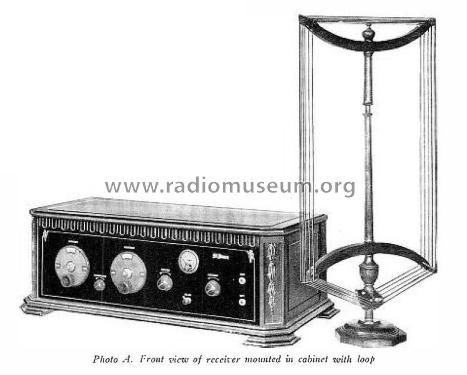
- Loudspeaker
- - This model requires external speaker(s).
- from Radiomuseum.org
- Model: St. James Super-Heterodyne - Oscillector, St. James
- Notes
-
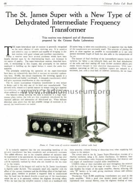
The St. James Super with a New Type of Dehydrated Intermediate Frequency Transformer
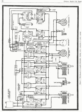
This receiver was designed, and all illustrations were prepared by the Citizens Radio Laboratory.
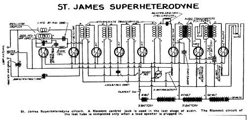
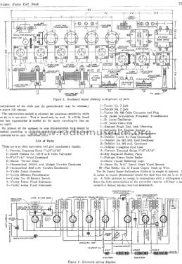
The circuit used in the St. James Super-Heterodyne consists of a Hartley oscillator, using a St. James Oscillector, 1st detector, four stages of intermediate radio frequency amplification, using St. James IF transformers, 2nd detector, and two stages of transformer coupled audio amplification.
UX201A tubes or their equivalent are used throughout the receiver with the exception of the last stage of audio. Here a UX112 power tube handles the output of the audio amplifier, thereby allowing 135 volts "B" battery to be used, giving maximum volume and without sacrificing tone quality.
Thordarson Type R -200 amplifying transformers are used in the audio amplifier. With a good cone speaker music and speech are reproduced with unusual fidelity, even the slightest shading of tone, volume, timbre and range. They have a wide range of amplification, giving good reproduction of notes from well into the bass up past the upper limits of audible frequency.
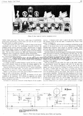
Two major controls are used; one for tuning the loop to the desired wavelength and the other for establishing resonance between the oscillator circuit and the intercepted signal. Regeneration, so helpful in receiving distant stations, is accomplished by inserting a .000045 mfd variable midget condenser in the plate circuit of the first detector tube.
The two major controls are .0005 mfd Hammarlund variable condensers with a straight-line frequency tuning characteristic.
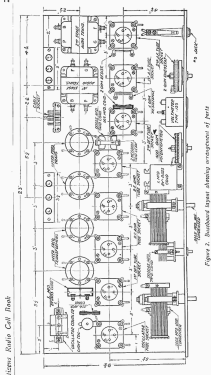
The St. James Oscillector is conveniently mounted by installing it on a Electrad grid leak mounting.
Benjamin UX cushion sockets are used throughout the receiver. A minimum amount of tube or microphonic noises will be experienced with this type of socket.
A Yaxley two-ohm air-cooled rheostat controls the first six tubes. The Jewell voltmeter shows, at all times, the voltage applied to the filaments of these tubes. Fixed resistances regulate the audio tubes.
Separate binding posts are provided for the "C" battery establishing the grid bias on the audio tubes. All battery leads are connected to the receiver by means of a Yaxley cable connector.
Citizens Radio Call Book & Technical Review 1926
- Mentioned in
- -- Original-techn. papers. (“Official Radio Service Manual” 1930, Editor Hugo Gernsback, reprinted 1984 by Vestal Press.)
- Literature/Schematics (1)
- -- Original prospect or advert (Citizens Radio Call Book & Technical Review 1926)
- Author
- Model page created by Pier Antonio Aluffi. See "Data change" for further contributors.
- Other Models
-
Here you find 4 models, 4 with images and 3 with schematics for wireless sets etc. In French: TSF for Télégraphie sans fil.
All listed radios etc. from Oscillector, St. James Laboratories; Chicago, lL