16B 16/16A-125 Version 3
Philco, Philadelphia Stg. Batt. Co.; USA
- País
- Estados Unidos
- Fabricante / Marca
- Philco, Philadelphia Stg. Batt. Co.; USA
- Año
- 1934
- Categoría
- Radio - o Sintonizador pasado WW2
- Radiomuseum.org ID
- 139600
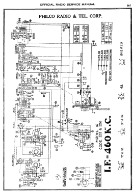
Haga clic en la miniatura esquemática para solicitarlo como documento gratuito.
- Numero de valvulas
- 11
- Principio principal
- Superheterodino con paso previo de RF; ZF/IF 460 kHz
- Gama de ondas
- OM y más de dos OC
- Tensión de funcionamiento
- Red: Corriente alterna (CA, Inglés = AC) / 115 Volt
- Altavoz
- Altavoz electrodinámico (bobina de campo)
- Potencia de salida
- 10 W (unknown quality)
- Material
- Madera
- de Radiomuseum.org
- Modelo: 16B 16/16A-125 [Version 3] - Philco, Philadelphia Stg. Batt
- Forma
- Sobremesa alto decorativa, similar a Capilla pero cuadrado (Tombstone, can have rounded edges).
- Ancho, altura, profundidad
- 17 x 22 x 12 inch / 432 x 559 x 305 mm
- Anotaciones
-
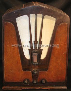
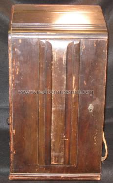
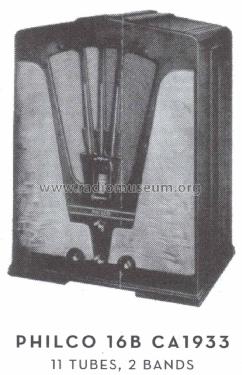
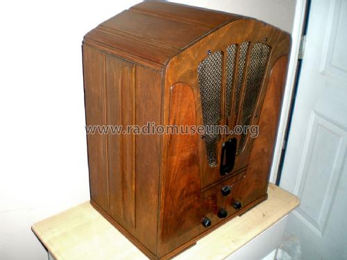
The 3rd version of the Philco 16B was introduced in Fall of 1934. The cabinet has a slightly higher peaked top than the 2nd version, with 4 broad bars running from the front of the cabinet to the back, two on either side of the peak. It uses the code 125 late chassis.
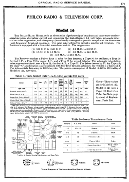
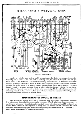
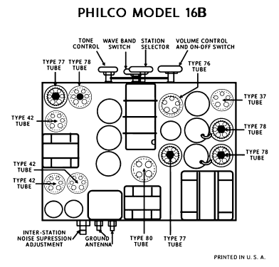
The model 16 series were high-end multi-band 11-tube radios sold by Philco for about 2 years spanning the 1933, 1934, and 1935 model years. There were two basic versions of the chassis referred to as 'early' and 'late'. Both the early and late chassis used a type 80 rectifier tube for the 16B table models, and a 5Z3 rectifier for the console models. Both chassis included dual IF-amp stages and a shadow meter (tuning aid). Both chassis were available in a version for 25-40 Hz power, and these chassis are marked as "16A" (where the -A suffix is a chassis suffix, not to be confused with the cabinet suffix on the main model number).
The early chassis used in 1933-34 included a QAVC ("quiet automatic volume control") squelch circuit to silence noise between stations. Squelch was implemented with a dedicated type 78 tube, and controlled with an on/off switch on the side and a potentiometer on the back to adjust the squelch level. The early chassis received five bands: 520-1500 kHz, 1.5-4.0 MHz, 3.2-6.0 MHz, 5.8-12.0 MHz and 11.0-23.0 MHz.
The late chassis (1934-35) eliminated the QAVC feature and repurposed its 78 tube to be an RF amplifier stage in the front end, thus maintaining the 11-tube count. The switch on the side of the cabinet was used as a bass-boost control called "Loudness". The late chassis covered a similar tuning range, but with only four bands: 550-1500 KHz, 1.5-4.1 MHz, 4.1-10.0 MHz, and 10.0-22.5 MHz.
The chassis codes are as follows:
Code 121: early chassis with 80
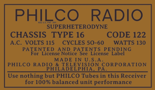
Code 122: early chassis with 5Z3
Code 123: unknown
Code 125: late chassis with 80
Code 126: late chassis with 5Z3
Code 127: unknown
There were fifteen versions of model 16 in different cabinet styles over the three-model-year span:
Four versions of the 16B cathedral/tombstone,
Three versions of the 16L lowboy console,
Four versions of the 16X floor-type console,
Three versions of the 16RX chairside,
A special 16CPX chairside.
Stein "Cathedral & Tombstone Radios" lists only 2 bands.
- Precio durante el primer año
- 90.00 $
- Procedencia de los datos
- Philco Radio 1928-1942
- Referencia esquema
- Rider's Perpetual, Volume 6 = 1935 and before
- Documentación / Esquemas (1)
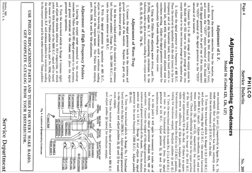
- Philco Service Bulletin #205
- Documentación / Esquemas (2)
- Cathedral & Tombstone Radios (page 190.)
- Autor
- Modelo creado por Thomas Albrecht. Ver en "Modificar Ficha" los participantes posteriores.
- Otros modelos
-
Donde encontrará 4086 modelos, 2222 con imágenes y 3734 con esquemas.
Ir al listado general de Philco, Philadelphia Stg. Batt. Co.; USA
Colecciones
El modelo 16B es parte de las colecciones de los siguientes miembros.


