38H (38, 38A)
Philco, Philadelphia Stg. Batt. Co.; USA
- Country
- United States of America (USA)
- Manufacturer / Brand
- Philco, Philadelphia Stg. Batt. Co.; USA
- Year
- 1933
- Category
- Broadcast Receiver - or past WW2 Tuner
- Radiomuseum.org ID
- 139505
Click on the schematic thumbnail to request the schematic as a free document.
- Number of Tubes
- 5
- Main principle
- Superheterodyne (common); ZF/IF 460 kHz
- Wave bands
- Broadcast (MW) and Tropical/Marine/Police Band(s) = 150-200m.
- Power type and voltage
- Storage and/or dry batteries / 135, 67.5, 2, -3, & -7 Volt
- Loudspeaker
- Permanent Magnet Dynamic (PDyn) Loudspeaker (moving coil)
- Material
- Wooden case
- from Radiomuseum.org
- Model: 38H - Philco, Philadelphia Stg. Batt
- Shape
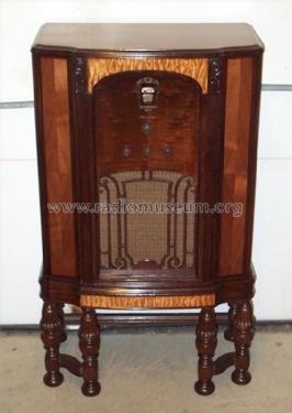
- Console, Highboy (legs > 50 %).
- Notes
- The model 38 series are battery operated 2-band sets with a variety of cabinet styles over several years.
There were five versions of the cathedral 38B: Version 1 (1933) has the classic spade-shaped speaker opening used on many Philco cathedral cabinets. Version 2 (1934) has an oval opening with three vertical bars and downward curving additional bars at the bottom. Version 3 (1934-35) has an oval opening with stepped features at the bottom. Version 4 (1935) is similar to version 3, but has a larger escutcheon opening and new dial design. Version 5 (1936) has a cabinet with a continuous arch shape starting from the base and multiple vertical bars in the speaker opening.
The model 38L lowboy has two versions: an early version (1933-34) with four narrow vertical bars at the edges of the speaker opening, along with other embellishment, and a late version (1934-35) with a single vertical bar through the center of the speaker opening, along with other embellishment.
There was also a highboy (1933) and a floor-type console (1935-36).
The chassis had an early version (used for 1933 and early 1934) with a type 15 mixer tube and a later version with type 1A6 mixer (used from mid 1934 onward). Chassis marked as model 38 have no ballast tube and are designed for use with a 2 volt storage battery for filaments. Those marked 38A have a ballast tube (type 6 early; type 1A1 late) and are designed for a dry battery (presumably 3 volts?) for the filament supply.
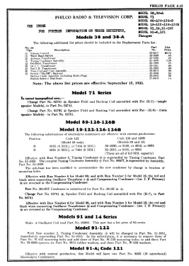
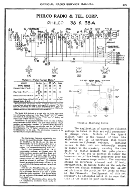
Two Philco schematics are available: code 121 with type 15 mixer (also found in Rider vol 4) and code 123 with 1A6 mixer.
- Source of data
- Philco Radio 1928-1942
- Circuit diagram reference
- Rider's Perpetual, Volume 4 = ca. 1934 and before
- Literature/Schematics (1)
- Philco 1928-36 Wiring Diagrams, Parts Lists, and Essential Service Data
- Author
- Model page created by Thomas Albrecht. See "Data change" for further contributors.
- Other Models
-
Here you find 4086 models, 2222 with images and 3734 with schematics for wireless sets etc. In French: TSF for Télégraphie sans fil.
All listed radios etc. from Philco, Philadelphia Stg. Batt. Co.; USA


