39F (39, 39A)
Philco, Philadelphia Stg. Batt. Co.; USA
- Country
- United States of America (USA)
- Manufacturer / Brand
- Philco, Philadelphia Stg. Batt. Co.; USA
- Year
- 1935
- Category
- Broadcast Receiver - or past WW2 Tuner
- Radiomuseum.org ID
- 50634
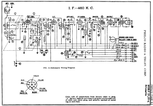
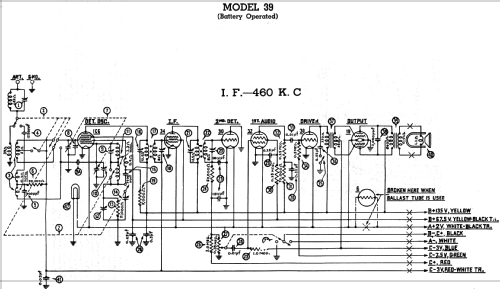
Click on the schematic thumbnail to request the schematic as a free document.
- Number of Tubes
- 6
- Main principle
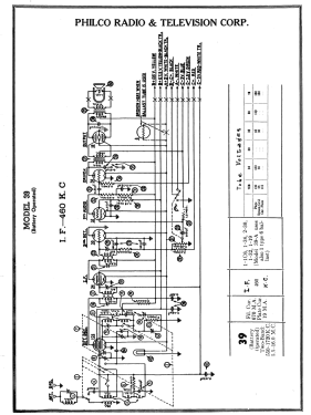
- Superheterodyne (common); ZF/IF 460 kHz; 3 AF stage(s)
- Tuned circuits
- 6 AM circuit(s)
- Wave bands
- Broadcast and Short Wave (SW).
- Power type and voltage
- Storage and/or dry batteries / 135, 67.5, 2, -3, -3, & -7.5 Volt
- Loudspeaker
- Permanent Magnet Dynamic (PDyn) Loudspeaker (moving coil)
- Material
- Wooden case
- from Radiomuseum.org
- Model: 39F - Philco, Philadelphia Stg. Batt
- Shape
- Table-Cathedral-Type (upright, round top or gothic arch, not rounded edges only).
- Notes
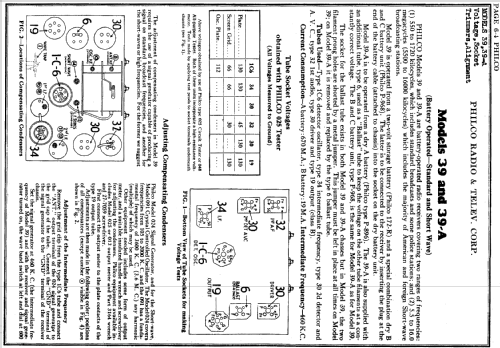
- There are two versions of model 39: the 39B cathedral (1934-35) and the 39F floor-type console (1935). Both are battery operated 2-band receivers.
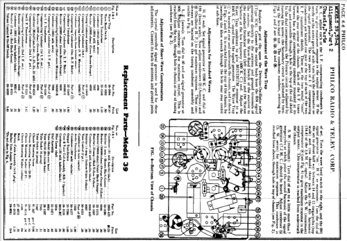
Chassis marked as model 39 have no ballast tube and are designed for use with a 2 volt storage battery for filaments. Those marked 39A have a type 6 ballast tube and are designed for a dry battery (presumably 3 volts?) for the filament supply. Three C batteries are required: two at 3V with separate connections for both + and -, and another at 7.5 V with a common + connection.
- Price in first year of sale
- 75.00 $
- External source of data
- Ernst Erb
- Circuit diagram reference
- Rider's Perpetual, Volume 6 = 1935 and before
- Mentioned in
- Philco Radio 1928-1942
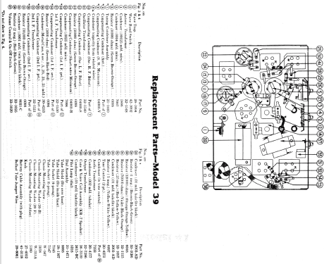
- Literature/Schematics (1)
- -- Schematic (Philco 1928-36 Wiring Diagrams, Parts Lists, and Essential Service Data)
- Other Models
-
Here you find 4085 models, 2222 with images and 3733 with schematics for wireless sets etc. In French: TSF for Télégraphie sans fil.
All listed radios etc. from Philco, Philadelphia Stg. Batt. Co.; USA