- Country
- United States of America (USA)
- Manufacturer / Brand
- Philco, Philadelphia Stg. Batt. Co.; USA
- Year
- 1940/1941
- Category
- Broadcast Receiver - or past WW2 Tuner
- Radiomuseum.org ID
- 50729
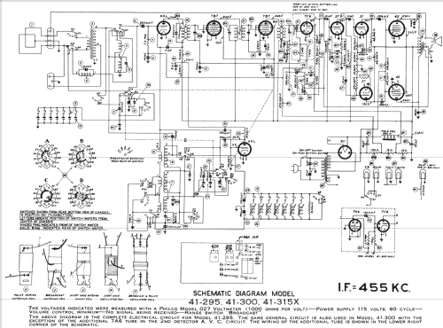
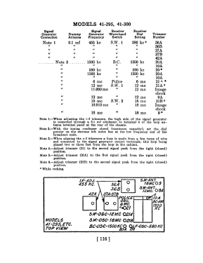
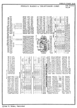
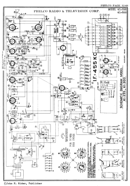
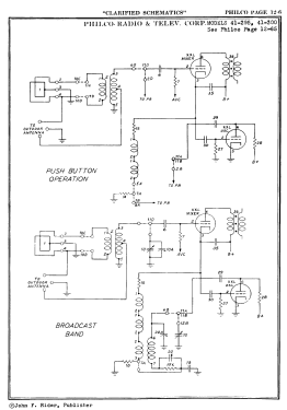
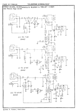
Click on the schematic thumbnail to request the schematic as a free document.
- Number of Tubes
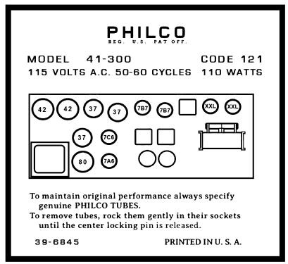
- 12
- Main principle
- Superheterodyne (common); ZF/IF 455 kHz
- Wave bands
- Broadcast plus more than 2 Short Wave bands.
- Power type and voltage
- Alternating Current supply (AC) / 115 Volt
- Loudspeaker
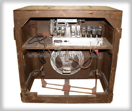
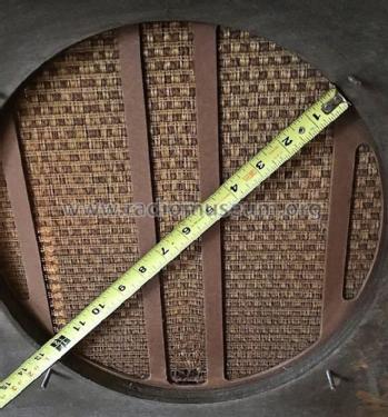
- Electro Magnetic Dynamic LS (moving-coil with field excitation coil)
- Power out
- 5 W (unknown quality)
- Material
- Wooden case
- from Radiomuseum.org
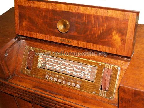
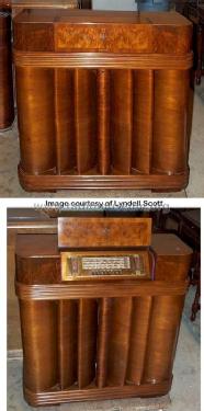
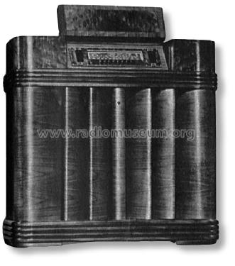
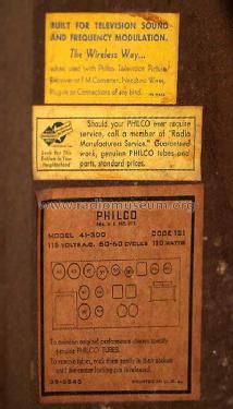
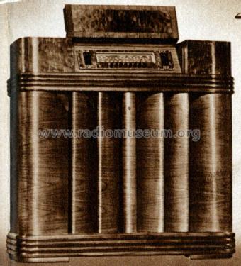
- Model: 41-300X - Philco, Philadelphia Stg. Batt
- Shape
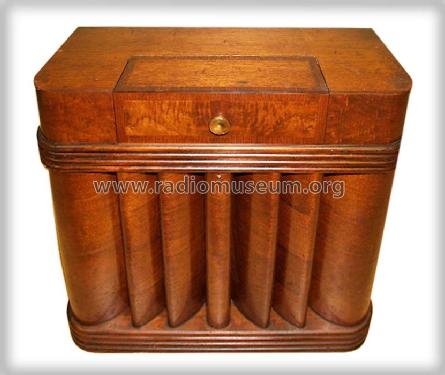
- Console with Push Buttons.
- Dimensions (WHD)
- 35.5 x 35.5 x 14 inch / 902 x 902 x 356 mm
- Notes
-
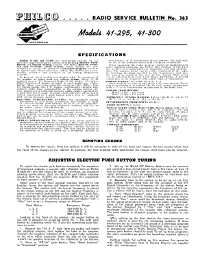
Model 41-300X has two IF stages. Tuning ranges: 540-1720 kHz; 2.3 - 7.0 MHz; 9.0 - 12.0 MHz; 13.5 - 18.0 MHz.
- External source of data
- Ernst Erb
- Source of data
- Collector's Guide to Antique Radios 4. Edition
- Circuit diagram reference
- Rider's Perpetual, Volume 12 = ca. 1941 and before
- Mentioned in
- The Radio Collector's Directory and Price Guide 1921 - 1965 (Philco Radio 1928-1942, Ramirez)
- Literature/Schematics (1)
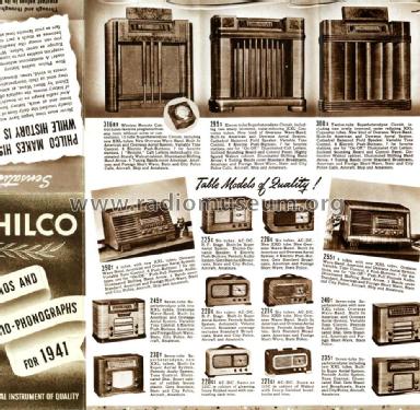
- Philco 1941 RMS Year Book
- Literature/Schematics (2)
- Pre-War Consoles
- Literature/Schematics (3)
- Philco Folder No. PR 798 for 1941.
- Other Models
-
Here you find 4085 models, 2222 with images and 3733 with schematics for wireless sets etc. In French: TSF for Télégraphie sans fil.
All listed radios etc. from Philco, Philadelphia Stg. Batt. Co.; USA
Forum contributions about this model: Philco, Philadelphia: 41-300X
Threads: 1 | Posts: 2
Help! I'm brnad new to this forum, so If I am violating any rules, Please advise and I will attempt to correct my methods.
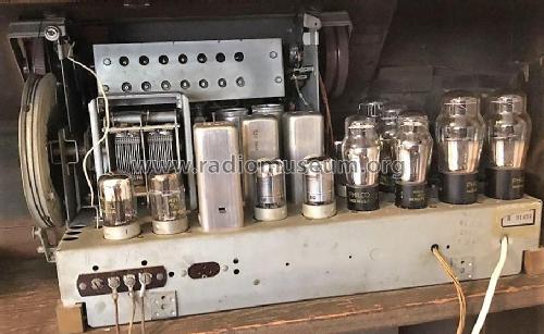
I am currently restoring a Philco 41-300 and have made a major error of not replacing wires, one at a time. I am attaching a picture of the tuning capacitor and need to have someone help me connect this now empty terminal to the right point in the radio.
If I am unable to properly upload my picture on the variable tuning capacitor, it would be the lug on the bottom of the left capacitor of the ganged two, as viewed from the rear of the unit.
Henry
Attachments
- Unconnected Tuning Capacitor (86 KB)
Henry Younce, 13.Jun.10
