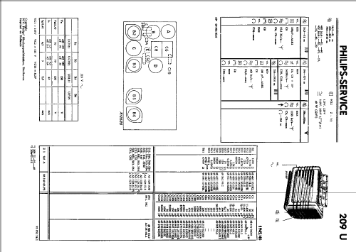
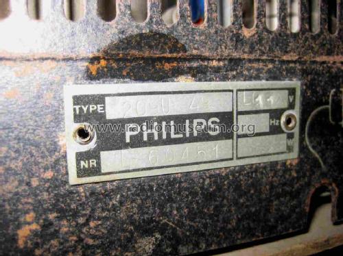
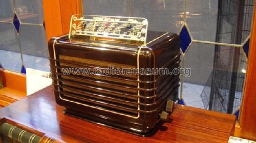
209U -49
Philips Belgium (Belgien)
- Paese
- Belgio
- Produttore / Marca
- Philips Belgium (Belgien)
- Anno
- 1945/1946
- Categoria
- Radio (o sintonizzatore del dopoguerra WW2)
- Radiomuseum.org ID
- 134083
Clicca sulla miniatura dello schema per richiederlo come documento gratuito.
- Numero di tubi
- 4
- Principio generale
- Supereterodina (in generale); ZF/IF 452 kHz
- N. di circuiti accordati
- 6 Circuiti Mod. Amp. (AM)
- Gamme d'onda
- Onde medie (OM), lunghe (OL) e corte (OC).
- Tensioni di funzionamento
- Alimentazione universale (doppia: CC/CA) / 125/220 Volt
- Altoparlante
- AP magnetodinamico (magnete permanente e bobina mobile) / Ø 5 inch = 12.7 cm
- Materiali
- Bachelite
- Radiomuseum.org
- Modello: 209U -49 - Philips Belgium Belgien
- Forma
- Soprammobile compatto/con bordi arrotondati/midget senza pulsantiera/tastiera.<= 35 cm (Sometimes with handle but for mains only).
- Dimensioni (LxAxP)
- 285 x 185 x 155 mm / 11.2 x 7.3 x 6.1 inch
- Annotazioni
-
Nachdem Widerstand R37 kurzgeschlossen ist, kann das Modell mit 110 / 200 V (AC/DC) gespeist werden.
Siehe die Übersicht mit allen 209U-Modellen am Ende dieser Modellseite unter "Dokumenten zu diesem Modell".
- Peso netto
- 3.3 kg / 7 lb 4.3 oz (7.269 lb)
- Prezzo nel primo anno
- 3,150.00 Bfr.
- Letteratura / Schemi (1)
- -- Original-techn. papers.
- Letteratura / Schemi (2)
- Philips Apparatenblad
| Übersicht Philips 209U-Modelle | 48 KB |
- Documenti su questo modello
- Autore
- Modello inviato da Wolfgang Bauer. Utilizzare "Proponi modifica" per inviare ulteriori dati.
- Altri modelli
-
In questo link sono elencati 596 modelli, di cui 572 con immagini e 343 con schemi.
Elenco delle radio e altri apparecchi della Philips Belgium (Belgien)
Collezioni
Il modello fa parte delle collezioni dei seguenti membri.
Discussioni nel forum su questo modello: Philips Belgium: 209U -49
Argomenti: 1 | Articoli: 6
Dear Radio Friends,
I have one Philips 209U.
To avoid an overvoltage (from the original 220V) I try to add one resistor to drop de difference from 220V to the actual voltage 230-240V.
But when I made the sum of all heater chain, pilot lamp and the mains droppers to find the actual heaters circuit value I got only 207,5V.
Heaters resistence:
R37=75
R39=190
R30=170 Sum= 435 ohms
Heaters current: 0,1 Amp so,heaters voltage dropping is : 435x0,1= 43,5V
------------------------------------------------------------------------------------------
Tube heaters voltage:
UCH21= 20V
UCH21= 20V
UBL21 = 55V
UY1N = 50V Sum= 145V
-------------------------------------------------------------------------------
Pilot lamp: 19V
------------------------------------------------------------------------------------------- Sum of heaters circuit,pilot lamp and main droppers:145+43,5+19 = 207,5 V
-------------------------------------------------------------------------------------------
Well, did I forget anything?
Do You know anything that helps me to understand why the final value is not 220V?
Thank You for your time
Best regards
Mário
Ps: Resistors Table is below
Mario Coelho, 25.Mar.06


