- Country
- Netherlands
- Manufacturer / Brand
- Philips; Eindhoven (tubes international!); Miniwatt
- Year
- 1949/1949
- Category
- Broadcast Receiver - or past WW2 Tuner
- Radiomuseum.org ID
- 29891
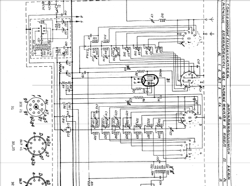
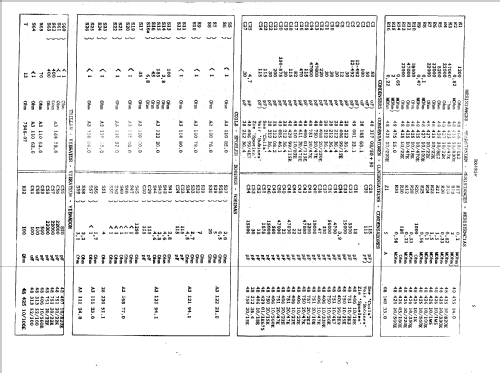
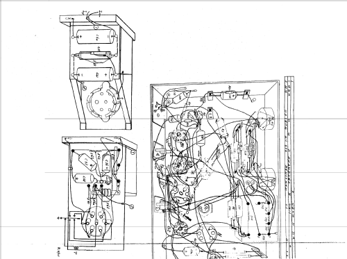
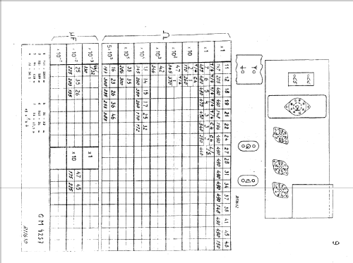
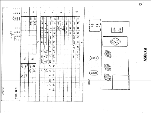
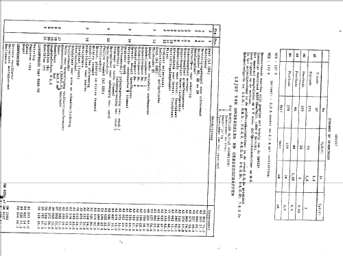
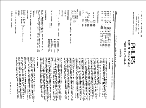
Click on the schematic thumbnail to request the schematic as a free document.
- Number of Tubes
- 4
- Main principle
- Superheterodyne (common); ZF/IF 452 kHz; 2 AF stage(s)
- Tuned circuits
- 6 AM circuit(s)
- Wave bands
- Broadcast, Long Wave and more than two Short Wave bands.
- Power type and voltage
- Storage Battery for all (e.g. for car radios and amateur radios) / 6 Volt
- Loudspeaker
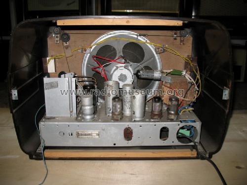
- Permanent Magnet Dynamic (PDyn) Loudspeaker (moving coil) / Ø 19 cm = 7.5 inch
- Power out
- 1.5 W (unknown quality)
- Material
- Bakelite case
- from Radiomuseum.org
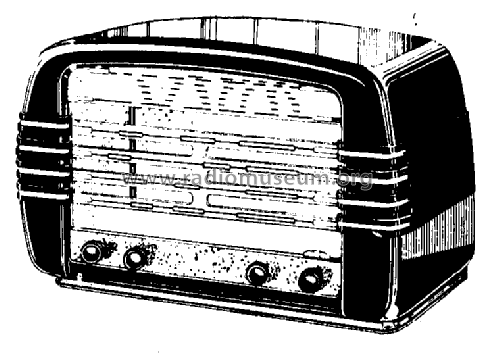
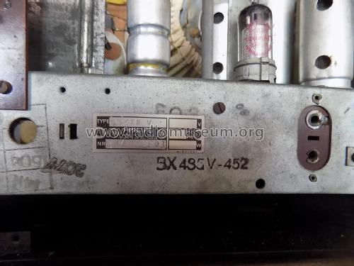
- Model: BX485V - Philips; Eindhoven tubes
- Shape
- Tablemodel, low profile (big size).
- Dimensions (WHD)
- 470 x 300 x 230 mm / 18.5 x 11.8 x 9.1 inch
- Notes
-
For a replacement of the vibrating DC/DC convertor: see this article.AM radio for external antenna:
- LW: 147,5 - 420 kHz.
- BC: 517 - 1620 kHz.
- SW1: 1,96 - 6 MHz.
- SW2: 5,94 - 9,46 MHz.
- SW3: 9,43 - 15,15 MHz.
- SW4: 11,67 - 18,75 MHz.
- SW5: 17,75 - 28,04 MHz.
Loudspeaker: 9686-05 (5Ω).Dial lamps: 2x 8045D (E10, 6.3V/320mA).
- Net weight (2.2 lb = 1 kg)
- 9.650 kg / 21 lb 4.1 oz (21.256 lb)
- Price in first year of sale
- 325.00 Hfl
- Source of data
- Technisch- Commercieel - Radio Vademecum Staleman
- Mentioned in
- -- Original-techn. papers.
- Literature/Schematics (1)
- -- Original-techn. papers.
- Author
- Model page created by Iven Müller. See "Data change" for further contributors.
- Other Models
-
Here you find 5273 models, 4419 with images and 3458 with schematics for wireless sets etc. In French: TSF for Télégraphie sans fil.
All listed radios etc. from Philips; Eindhoven (tubes international!); Miniwatt
Collections
The model is part of the collections of the following members.
Forum contributions about this model: Philips; Eindhoven: BX485V
Threads: 1 | Posts: 1
Afin de conserver le vibreur d'origine et d'obtenir un meilleurs rendement, j'ai réalisé ce convertisseur de remplacement dont je vous propose le schéma et un exemple de réalisation s'intégrant dans le BX485V à la place de celui d'origine. Merci d'avance d'en prendre connaissance.
P-Y DEBAES
Attachments
- Convertisseur de rempl. (19 KB)
- BX485_Conv2_doubleur et transfo (31 KB)
- BX485V_Conv1_driver et Mosfet (32 KB)
- BX485V_Conv3_blindage (32 KB)
Pierre-Yves Debaes, 28.Jul.08
