- Country
- United States of America (USA)
- Manufacturer / Brand
- Radio Wire Television Inc.; New York - see also Lafayette
- Year
- 1935/1936
- Category
- Broadcast Receiver - or past WW2 Tuner
- Radiomuseum.org ID
- 52729
Click on the schematic thumbnail to request the schematic as a free document.
- Number of Tubes
- 24
- Main principle
- Superhet with RF-stage; ZF/IF 456 kHz; 3 AF stage(s)
- Tuned circuits
- 8 AM circuit(s)
- Wave bands
- Broadcast, Long Wave and more than two Short Wave bands.
- Details
- Record Player (perh.Changer)
- Power type and voltage
- Alternating Current supply (AC) / 115; 135; 150; 220; 250 Volt
- Loudspeaker
- 2 Loudspeakers
- from Radiomuseum.org
- Model: C-95 - Radio Wire Television Inc.;
- Notes
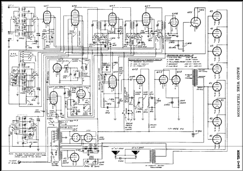
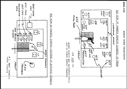
- This chassis C-95 is made by an other factory for Radio Wire Television with trade name Lafayette. It has probably been used by Lafayette for the models C-95, C-96 and C-97. The only difference we can find is the use of a tube 76 instead of a 45 as a rectifier - both tubes can do the same job. We give here the description found at Lafayette:
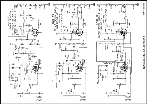
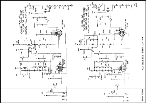
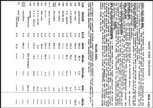
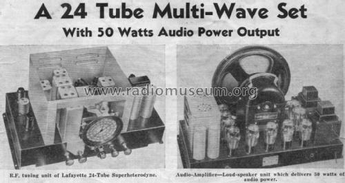
Power output stage class AB triodes deliver up to 50 watt to the 12" "Auditorium" speaker and the 10" high frequency speaker "to span the entire audible range exactly as broadcast by the new high-fidelity stations. Step wise expanding selector makes possible high-fidelity response of 60 to 8000 cycles with good adjacent channel selectivity or hairline selectivity by varying the intermediate frequency band width acceptance. Dual chassis. Easy reading sector dial in which only the band in use is illuminated in distinctive coloring. Two speed planetary drive with split knob control. Automatic tone control (ATC) to reduce noise between stations. Beat oscillator. 19 tuned circuits (what is surely wrong if we count only tuned circuits which enable selectivity and/or sensitivity). Dual IF amplifier. Five distinct bands covering a range of 140 kc to 30 megacycles (8 to 2,050 meters) as follows: 8 - 16; 16 - 57.5; 57 - 187; 187 - 555 and 850 - 2050 meters." We can only say that 30 mc is not 8 m ... Rider's: 8.125 - 16.6; 16.6 - 57.5; 57.5 - 187.5; 187.5 - 554 and 872 - 2100 meters for this chasssis here. This is pretty much the same.
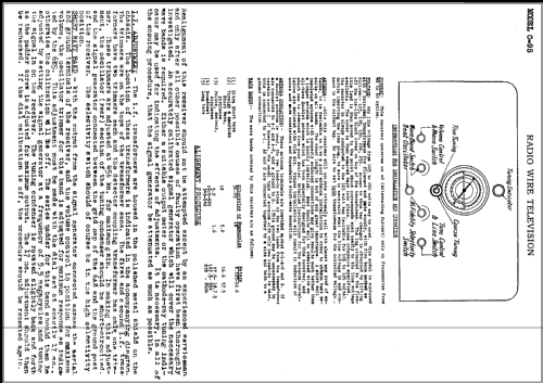
Lafayette C-95 chassis is supposed to have the following dimensions: receiver chassis 19.125" wide, 10.25" high and 12.125" deep. amplifier-power supply chassis 22.25" wide 14" high and 11.25" deep. Rider's shows the front with the knobs: Volume control and Phono switch; Wave Band Switch; in the middle: below Beat Oscillator, above Coarse and fine tuning; HiFidelity; Selectivity switch. Lafayette does not show the lower knob for the beat oscillator but otherwise everything seems to be the same and also the parts shown for the main chassis are equal.
- Circuit diagram reference
- Rider's Perpetual, Volume 18 = 1949 and before
- Literature/Schematics (1)
- From Short Wave Craft for December 1935, Page 469
- Author
- Model page created by Peter Rutishauser. See "Data change" for further contributors.
- Other Models
-
Here you find 106 models, 20 with images and 105 with schematics for wireless sets etc. In French: TSF for Télégraphie sans fil.
All listed radios etc. from Radio Wire Television Inc.; New York - see also Lafayette