- Land
- Grossbritannien (UK)
- Hersteller / Marke
- Radiomobile Ltd., Cricklewood Works, London
- Jahr
- 1959 ?
- Kategorie
- Autoradio, evtl. kombiniert mit Tonspeichergerät
- Radiomuseum.org ID
- 150380
-
- anderer Name: S.Smith and Sons
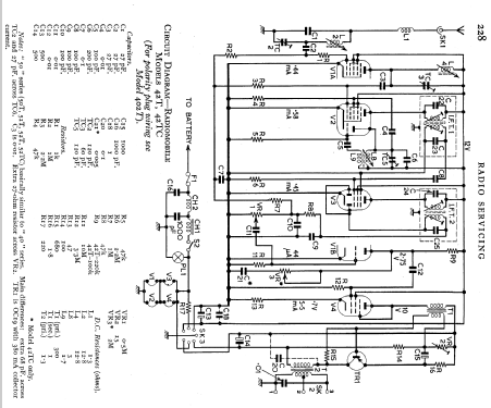
Klicken Sie auf den Schaltplanausschnitt, um diesen kostenlos als Dokument anzufordern.
- Anzahl Röhren
- 4
- Anzahl Transistoren
- 1
- Halbleiter
- 2N178
- Hauptprinzip
- Super mit HF-Vorstufe; ZF/IF 470 kHz; 3 NF-Stufe(n)
- Anzahl Kreise
- 7 Kreis(e) AM
- Wellenbereiche
- Mittelwelle, keine anderen.
- Betriebsart / Volt
- AKKU-Speisung (für alles, z.B. bei Autoradios und Amateurgeräten) / 12 Volt
- von Radiomuseum.org
- Modell: 52T - Radiomobile Ltd., Cricklewood
- Form
- Chassis - Einbaugerät
- Bemerkung
- Basicaly similar to model 42T, except changes to 3 capacitors.
- Datenherkunft
- -- Schematic
- Schaltungsnachweis
- Radio and TV Servicing books (R&TVS) book
- Autor
- Modellseite von Keith Staines angelegt. Siehe bei "Änderungsvorschlag" für weitere Mitarbeit.
- Weitere Modelle
-
Hier finden Sie 119 Modelle, davon 47 mit Bildern und 64 mit Schaltbildern.
Alle gelisteten Radios usw. von Radiomobile Ltd., Cricklewood Works, London
Forumsbeiträge zum Modell: Radiomobile Ltd.,: 52T
Threads: 1 | Posts: 4
Hello all,
new person here. I recently purchased the above radio. On the bottom of it there is a red plug, which according to the adjacent information sticker converts the radio to positive ground. Indeed, I did use a 12 VDC source (an old computer power supply), and connected the +12 VDC to the ground, and the ground wire from the power supply to the power wire of the radio, and it worked! Actually, it was surprisingly clear AM reception for the sparse AM radio we have here in Prescott, AZ. According to the sticker if I were to have a black plug, the radio could be converted to negative ground. I wish to use this radio in a restored automobile that will have a negative ground. Here are my questions, please:
1. I am presuming there is no way I could find a vintage black plug to convert to negative ground. Would there be a way to add jumper wires inside the radio to convert to negative ground? I am handy with a soldering station, in the past I have diagnosed and repaired pinball machine circuit boards, but I am brand new to tube radios. Just observing the schematic I would think it would be possible, but I do not wish to blow capacitors! :-) I am thinking the SK3 notation on the schematic is referring to the red/black plugs I was referring to.
2. Could someone please observe the schematic and tell me where the loudspeaker output is? Again, from my newbie observation I would guess the notation SK2 is it, but I wish confirmation (or rejection) of this assertion. :-)
3. If I do have to open up the box for jumpers, would it be helpful to upload photos of the electronics?
Thank you in advance for any and all information you can give me.
Regards, Dan
Dan Beck, 16.Dec.12