Radiola IV (4)
RCA (RCA Victor Co. Inc.); New York (NY)
- Country
- United States of America (USA)
- Manufacturer / Brand
- RCA (RCA Victor Co. Inc.); New York (NY)
- Year
- 1922
- Category
- Broadcast Receiver - or past WW2 Tuner
- Radiomuseum.org ID
- 54627
-
- alternative name: RCA Manufacturing || Victor Talking Machine
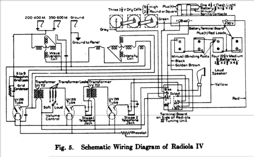
Click on the schematic thumbnail to request the schematic as a free document.
- Number of Tubes
- 3
- Main principle
- TRF with regeneration; 2 AF stage(s)
- Wave bands
- Broadcast only (MW).
- Power type and voltage
- Dry Batteries
- Loudspeaker
- Horn
- Material
- Wooden case
- from Radiomuseum.org
- Model: Radiola IV - RCA RCA Victor Co. Inc.; New
- Shape
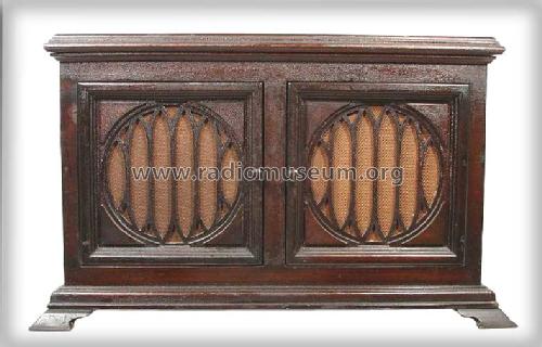
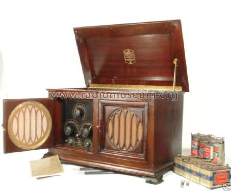
- Tablemodel, low profile (big size).
- Notes
- Built in speaker. 2 front doors.
Although already specified July 25, 1922 the Radiola IV was not available until after the Christmas selling season due to shortage of UV199. The tubes could not be made in necessary quantities.
- Price in first year of sale
- 275.00 $
- External source of data
- Ernst Erb
- Source of data
- Radio Collector`s Guide 1921-1932
- Circuit diagram reference
- Rider's Perpetual, Volume 1 = 1931/1934 (for 1919-1931)
- Mentioned in
- Collector's Guide to Antique Radios 4. Edition
- Literature/Schematics (1)
- Radio Manufacturers of the 1920's, Vol. 3
- Literature/Schematics (2)
- Radio Broadcast, Jan. 1924. p. 265
- Other Models
-
Here you find 5135 models, 3239 with images and 4175 with schematics for wireless sets etc. In French: TSF for Télégraphie sans fil.
All listed radios etc. from RCA (RCA Victor Co. Inc.); New York (NY)
Museums
The model Radiola can be seen in the following museums.
Forum contributions about this model: RCA RCA Victor Co.: Radiola IV
Threads: 1 | Posts: 1
Thanks to Ramon Gancedo, Madrid, Spain who decided to scan some pages of the RCA-Manual for www.radiomuseum.org and Thomas Günzel, Ulm, Germany who did the OCR-Recognition I am (after correcting OCR - there may be still some small errrors) able to present you an article which shows the function, the build up and the operation of a Regenerative Receiver and Amplifier. We now worked the same way for model Radiola IV.
INTRODUCTION
RADIOLA IV is a complete dry cell operated vacuum tube regenerative receiver and amplifier, including a self-contained loud speaker. The only accessories not provided are the antenna equipment and ground connection. Full instructions are given in another section for the erection of antenna and for the ground connection.
UNPACKING
UNPACKING Radiola IV is so important a step that it will be found well worth while to follow these directions carefully. Radiola IV is wrapped in waxed paper as a protection against moisture, and is suspended in a special shock absorbing cradle. The rounded openings at either side of the case allow place for the hands to grasp the entire cradle and lift it free from the case. Next cut away the suspension strings of the cradle, care being taken that Radiola IV is subjected to no severe jars as it is removed.
Remove waxed paper; turn cabinet bottom side up, placing it on a smooth soft surface to avoid scratching or marring the finish. When turning or handling cabinet, care should be used to prevent cover from opening, thereby damaging the finish, stay joint or hinges.
A package containing four (4) wooden feet and eight (8) screws will be found in bottom of packing case, held in place by burlap strip nailed to cleat.
These wooden feet are marked 1, 2, 3, 4, corresponding to same marks on bottom of cabinet. Feet should be screwed to cabinet and cabinet turned over and placed on its feet. Care should again be used in turning to keep cover closed.
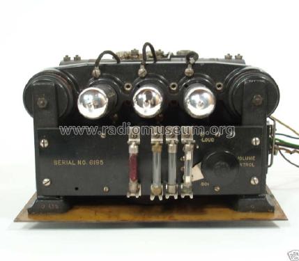
The top of the case should now be lifted, whereupon the automatic catch will hold it in position. This exposes the vacuum tube cradle and the battery racks. No attempt should be made to remove the box to the right before the battery terminal board which holds it has been removed: loosening the thumbscrews at either end will accomplish this.
The box contains a pair of sensitive telephone receivers, a plug to accommodate the telephone cord tips, flexible silk covered connection cords with plugs for connecting to the antenna and ground posts of the antenna protector, two short connectors for use in connecting the three dry cells ("A" battery) and one UV-199 Radiotron. In the left rear of the cabinet interior there is a three compartment casting for holding the dry cells ("A" battery) in place.
For shipment, these compartments are used to hold three of the four vacuum tubes supplied with the set. The thumbscrews of the large clamp should be loosened to remove the tubes in their wadding.
The necessary batteries specified below are packaged separately and will be supplied by the retail dealer.
BATTERIES REQUIRED
A. Three dry cells 1½, volts each, for lighting the filaments, 2¨ý in. diameter or square by 6½ in. high, such as Columbia No. 6, Mesco "Red Seal," Burgess "Super Six," or equivalent. Either the square or round style may be used.
B. Four "B" or plate batteries, each 22 ½ volts, 2 9/16 in. x 2¾ in. x 4¨û in., such as Burgess No. 5156 BP, Eveready No. 768, or equivalent.
C. One "C" or grid bias battery, 4½ volts, ¨ý in. x 1¨þ in. x 2¼ in., such as Burgess No. 432, Eveready No. 751, or equivalent.
INSTALLING BATTERIES
BATTERY installation may begin with the small 4½-volt grid bias battery, similar to that used in flat pocket flashlights. This should be inserted in the special compartment provided in the rear of the right hand or "B" battery rack, in such position that its protruding brass strips will make connection with the spring contacts projecting to the rear from the under side of the long battery terminal board which holds the "B" batteries in place.
The negative (long post) of the grid bias battery should be placed toward the right. The battery clamp should not be fastened down, however, until the four oblong, 22½-volt "B" batteries have been placed in their compartments. The four "B" batteries are placed side by side in their compartment as shown in Fig. 1. Counting from the left, the first and third batteries are located with their (-) binding posts toward the rear, and the second and fourth batteries with their ( + ) red leads toward the rear.
Next, the three 1½ -volt dry cells should be placed in the rack at the left and made secure by tightening the thumbscrews. These are connected in series by means of the two short connectors which come packed in the box with the head telephones (see Fig. 1). Starting from left to right on the three cells in their rack, fasten one end of a connector to the minus or edge post of cell No. 1 at the extreme left, to the plus or center post of cell No, 2. The second connector should be used to connect cells No. 2 and 3 in the same manner. Then the several wires which attach to the terminal board of the radio unit should be connected to the different batteries as follows:
1. The gray wire tagged "A+4½ V." connects with the center (Positive) post of the "A" dry cell at the extreme left.
2. The green wire tagged " + Bias" connects with the left hand terminal post, marked " + Bias" on the battery terminal board.
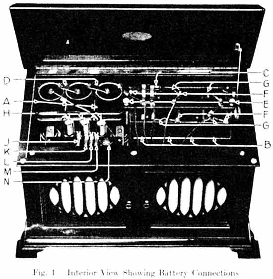
A—l½-volt dry cells ("A" battery—square or round style may be used).
B—22½-volt dry batteries ("B" battery).
C—4½ -volt dry battery ("C" battery—long blade toward right).
D—Jumpers.
E—Clamping screws for battery board.
F—Minus (—) binding post terminals
G—Plus (+) red leads.
H—UV-199 Radiotrons.
J—6 to 9 Megohm grid leak.
K—Highest Value Transformer Resistance.
L—Medium Value Transformer Resistance.
M—Lowest Value Transformer Resistance.
N—Volume Control.
3. The golden brown wire tagged "-Bias" connects with the next terminal post to the right marked "-Bias" on the battery terminal board.
4. The small green wire jumper marked "A-4½ V." attached to the terminal marked "+Bias" connects with the edge (-) post of the third "A" dry cell.
5. The black wire tagged "-90 V." connects with the negative (-) binding post terminal in the left rear corner of the left hand "B" battery.
6. The yellow wire tagged "B+45 V." connects with the binding post terminal in the left rear corner of the third "B" battery from the left.
7. The red wire tagged "+90 V." connects with the right hand terminal post marked "+90 V." on the battery terminal board.
8. The red flexible lead ( + ) in the left rear corner of the right hand "B" battery is also connected to this terminal marked " + 90 V."
9. The three remaining red flexible "B" battery leads (positive) are connected to the negative binding post terminals of the adjacent battery to the right.
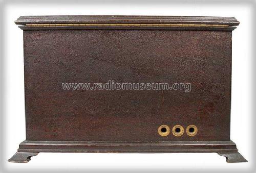
10. The two brown silk covered flexible wires with plugs connect with the Antenna and Ground posts of the antenna protector and plug into their respective jacks at the rear of Radiola IV. The plug with the red insert should be used as the Antenna Plug.
OPERATION
Vacuum Tube Precautions. Due to the unusually small filament, the vacuum tubes should be very carefully handled.
Before inserting the tubes, be sure that the filament rheostat on the panel is "OFF."
Do not forget to turn the filament pointer to "OFF" when the set is not in use, for if tubes are left lighted, their life and the life of the battery will be prematurely shortened. Each time the tubes are used, it is well to look inside to see that all three are lighted and not at excessive temperature.
Insert one tube in each of the three sockets, and put the extra tube, in its wrapping, down in the bottom of the cabinet. In putting the tubes into the sockets, turn the tube until the pin drops into the slot, then turn slightly to the right.
Before closing the cover, be sure that the small "volume control" switch on the top of the radio unit is turned toward the rear of the set.
Now turn on the filaments as explained in next paragraph, set the "intensity" pointer at zero and the set may be tuned.
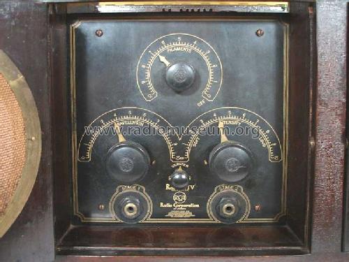
Filament. The "filament" knob controls the brilliancy of the filaments. When the batteries are new, the proper setting of the filament pointer should be somewhere between 1 and 4. As the batteries grow older, it will be necessary to turn the pointer further to secure normal operation.
When a station is heard, slowly decrease the filament brilliancy until the signal strength begins to diminish, then increase the brilliancy just sufficient to restore full signal strength. Burning the filaments brighter than necessary decreases the life of the vacuum tubes.
Tuning. Tuning involves the manipulation of the wavelength control so that the apparatus may be adjusted for a maximum signal from the broadcasting station. First, the head telephones should be connected to the plug and inserted in the jack marked "stage 1." After adjustments have been made," the plug may be removed, which will automatically throw on the loud speaker.
The "wavelength" knob should be rotated very slowly back and forth over its scale until a voice or music is heard in the head telephones. When the wavelength control has been adjusted at the point where the sound is loudest, the next step is to increase its intensity.
The final careful adjustment of the "wavelength" control should be made by turning the "vernier" knob in the bottom center of the panel.
Intensity. For the proper regulation of the "intensity" control, one should grasp the wave changing control with the left hand, and the "intensity" knob with the right. Now, with the right hand, advance the "intensity" pointer to the position where best increase of signal strength is obtained.
Should it be advanced too far, a click will be heard in the telephones and then all signals will have a "mushy" sound. At this point the receiver becomes a transmitter and seriously interferes with neighboring radio receivers. This condition of oscillation must be avoided, but if it does occur, immediately turn the intensity control backward until the signal clears up.
When the "intensity" knob has been adjusted to the position at which it works loudest and clearest, both the "wavelength" and "intensity" pointers may be turned slightly back and forth, until the utmost degree of regeneration is obtained. The point just before oscillations start is the most sensitive and most selective condition of the receiver. There is also a condition in which the tubes are on the verge of oscillating. The signals are heard, but the quality is very poor. This condition can be avoided by turning the "intensity" control slightly in the direction of zero.

If the signals are coining from a nearby station, they may be so powerful that the amplifying tubes increase them to an intensity greater than necessary. This will also give poor quality of reproduction.
The little switch inside the set and adjacent to the tubes gives three steps of decreasing intensity with increasing clarity, as the switch is turned toward the front of the set. Be sure to turn it back when you wish to listen for distant signals. Further reduction in signal strength may be obtained by using a small antenna, by turning the "intensity" knob counter-clockwise, or by slightly detuning the signal with the "wavelength" knob.
This simultaneous adjustment of "wavelength" and "intensity" knobs is simple enough for any one to perform, yet there is a proficiency which comes of practice that will enable one to make the more careful adjustments necessary to the tuning and amplification of more distant stations.
To obtain extreme ranges from Radiola IV, the head telephones should be plugged in the jack of "stage 2" on the control panel. The loud speaker is automatically disconnected when this is done. When the head telephones are not in use, they may be placed inside the cabinet, over the horn.
FC— Filament Control.
WC—Wavelength Control.
IC— Intensity Control.
VC—Vernier Control.
OC—First Stage Telephone Jack.
TC— Second Stage Telephone Jack.
GENERAL INFORMATION
Care and Maintenance. The antenna and ground should be inspected occasionally to see that connections have not become corroded, and that insulators are not dirty or broken. Poor connections or bad insulators will increase the energy losses in the system and will give poor and irregular reception. It will also be well, after the set has been in service a year, to put a drop (not more) of oil on the intensity and wavelength shaft bearings inside the set. Clean the exterior surface of the cabinet as you would any fine piece of furniture.
Replacements. The batteries and the tubes are the only parts that will need to be replaced, unless some other part is accidentally broken.
To replace the batteries, first carefully disconnect all wires from the batteries themselves, and remove the old batteries from the racks. It is not necessary to disconnect the leads from terminal boards.
POSSIBLE DIFFICULTIES
Faulty Operation, Its Causes and Remedies. Anything which tends to increase resistance, or decrease insulation, will give poor operation. As the batteries grow old, they decrease in voltage, and increase in resistance. As the tubes grow very old, the filaments become less and less effective. Each fault however, suggests its own remedy.
1. Poor connections in antenna or ground wires or defective insulation of antenna.
2. "filament" control not properly adjusted.
3. Batteries exhausted (indicated by low filament brilliancy, weak signals and distortion).
4. Battery connections improperly made, poor or broken.
5. "intensity" control not in correct adjustment.
6. Poor or broken connections in telephone cord or plug.
7. Inoperative vacuum tubes.
8. Glass tube resistances fallen out of their mountings.
If you are not sufficiently familiar with the technical points enumerated above call in the nearest Radiola denier to assist you.
In general the troubles common to radio sets and in fact all electrical apparatus are reduced to a minimum in the Radiola IV
ERECTION OF ANTENNA
Outdoor Antenna. The receiving antenna is the exposed conductor by means of which a small portion of the energy sent out by the distant transmitter is collected. So far as possible, it should be placed above the tops of surrounding buildings and trees and must be thoroughly insulated so that no portion of the very small amount of energy picked up may be lost.
A span of about 80 feet is desirable and should be 25 feet or more above the ground. In general, reception improves with increased height. If the suggested length and height cannot be secured approach them as nearly as possible. The antenna should be at right angles to electric light, power, and telephone wires and, if practicable, at least 15 feet distant from them. It must not be touched by any object except the insulators. The same precautions apply to the lead-in wire, which should be a continuation of the antenna wire without any joints and run as directly as possible to the receiver.
The ground wire (14 B.&S. gauge) should be connected as directly as possible by means of a ground clamp to the house water pipe, or to a pipe driven deeply into moist ground. The ground wire and the pipe should be well scraped and cleaned at the point of connection. For the protector use Model UQ-1310 which has been approved and listed by the Underwriters laboratories. Install it where the lead-in wire comes into the house. The antenna system as described and as shown in the diagram is in accordance with National Electric Code Standards.
The instrument should be located conveniently near to the protector. Attach the plug cords to the antenna and ground terminals of the protector, and plug them into the jacks in the rear of the set. There are two antenna jacks, one for wavelengths between 200 and 400 meters, and one for wavelengths between 350 and 600 meters. Since most of the broadcasting stations send on wavelengths between 360 and 400 meters, they may be received with the antenna plugged into either of the jacks. If the low wave jack is used, they will tune between 7 and 10, while if the high wave jack is used they will tune between 0 and 3 on the wavelength dial.
Indoor Antenna. In receiving nearby stations, an indoor antenna even as short as 20 to 30 feet will usually give satisfactory results and will have considerable selectivity. This is because of the extreme sensitiveness of the instrument. The indoor antenna may consist of a wire run the length of the attic or just below the ceiling of an ordinary size living room. The same ground connection is used as previously described.

Edit: 23rd March: Small OCR-faults corrected.
Ernst Erb, 22.Mar.07

