Corner Radio Console Cabinet
Rockford Novelty Furniture Co., Johan O. Bergman; Rockford, IL
- Country
- United States of America (USA)
- Manufacturer / Brand
- Rockford Novelty Furniture Co., Johan O. Bergman; Rockford, IL
- Year
- 1928
- Category
- Cabinet only
- Radiomuseum.org ID
- 263296

Click on the schematic thumbnail to request the schematic as a free document.
- Wave bands
- - without
- Power type and voltage
- No Power needed
- Material
- Wooden case
- from Radiomuseum.org
- Model: Corner Radio Console Cabinet - Rockford Novelty Furniture Co.
- Shape
- Miscellaneous shapes - described under notes.
- Notes
-
Console radio cabinet designed to look like a Baby Grand piano and constructed to fit in a corner. Approximate measurements are: 46" tall. 32" wide. 30 deep. Front inside radio compartment measures 29" wide 10" deep by 8.5" tall
- Author
- Model page created by Mark Skala. See "Data change" for further contributors.
- Other Models
-
Here you find 1 models, 1 with images and 1 with schematics for wireless sets etc. In French: TSF for Télégraphie sans fil.
All listed radios etc. from Rockford Novelty Furniture Co., Johan O. Bergman; Rockford, IL
Collections
The model Corner Radio Console Cabinet is part of the collections of the following members.
Forum contributions about this model: Rockford Novelty: Corner Radio Console Cabinet
Threads: 1 | Posts: 1
Text from the patent of 1928 for a console radio cabinet - OCR - without correction:
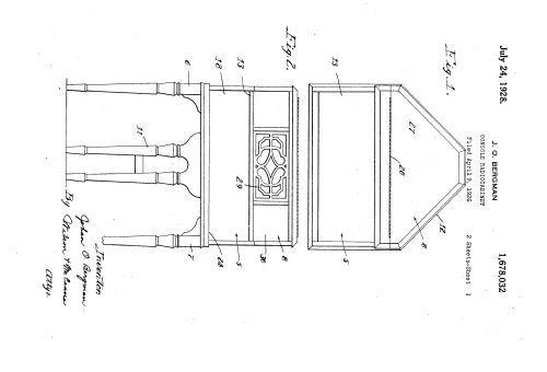
This invention relates to radio cabinets generally but is more particularly concerned with the provision of a console type cabinet embodying certain novel and advantageous features and presenting a striking similarity to the cabinet of a baby grand piano.
The principal object is to provide a console cabinet of the kind mentioned having a front instrument compartment and a rear horn and battery storage compartment, the latter having the vertical side walls thereof converging rearwardly to simulate the harp shape of a baby grand piano and also enable the placing of the cabinet to advantage in the corner of a room with'the' instrument compartment diagonally disposed and the storage compartment utilizing the space therebehind.
Another object is to provide a cabinet of this kind having a relatively shallow front compartment to contain the instruments and a relatively deep compartment therebehind having a front wall projecting above the front compartment at the back thereof provided with a grilled opening behind which a horn disposed in the rear compartment may be arranged, the horn furthermore being preferably mounted, on a hinged lid to be swung into and out of the compartment so as to afford access to the storage space therebeneath.
L Still other features of the cabinet are the provision of a hinged lid for the front compartment affording ready access to the instruments and a hinged fall-for the front of said compartment to expose the radio panel therebehind and to provide a convenient and comfortable arm rest while using the radio.
The invention is illustrated in the accom panying drawings, wherein- Fig. 1 is a plan view of a cabinet embodying the novel features referred to;
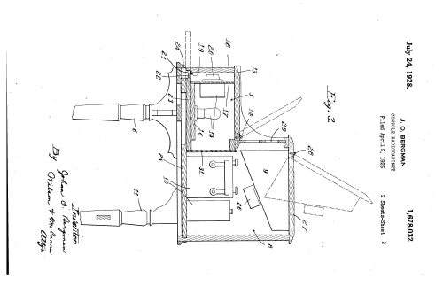
Fig. 2 is a front view thereof; and v V Fig. 3 is an'enlarged central vertical'section therethrough indicating in dotted lines how the front fall may be lowered and the two lids raised, the one lid carrying the horn with it out 'of the cabinet in amanner briefly referredto above and more fully described hereinafter.
' The cabinet of the present invention is of the console type and is designed to preier gt a striking resemblance generally to a a the Za in and piano. Thus, generally stated, et embodies a front 1nstrumentc0m-' 1926. Serial No. 100,781.
partment- 5 extending the width of the cabinet and supported by laterally spaced front legs 6 and 7 thereby simulating the front of a baby grand piano w th the closed comparthouse the loud speaker horn'9 and also to store the A and B batteries 10. A rear douole leg 11 underlies the rear compartment 8, as shown, and in front elevation, furthers the resemblance to the baby grand piano, as Wlll be clear from Fig. 2. The rear compartment 8 has rearwardly converging vertical s1de walls 12 to simulate the harp shaped soundbox portion of a baby grand piano. The s1de walls 12 extend approximately at right angles so that the cabinet is particularly well adapted and, in fact, is intended for standing in the corner of the room, with the front disposed diagonally relative thereto. Thus, the storage compartment utilizes the space which would otherwise be wasted and the cabinet, besides having a generally improved appearance, is better ada ted for use 1n the homeor in apartments w ere the use of space to good advantage is particularly desirable.
The front compartment 5 has a lid 13 hmged at 14 to be raised, as indicated in' dotted llnes, so as to afford access to the instruments such as those diagrammatically represented at 15. These are preferably mounted on a base 16 andpanel 17 which may or may not be removably mounted with-- in the compartment 5, as desired. A fall 18 at the front of the compartment is hinged, as at 19, near the bottom thereof to be low-' ered to the dotted line position shown and thus expose the dials 20 on the panel- 17. Thefall 18 base rabbeted loweredge, as shown at 21, arranged in the lowered posi tion of the fall to underlie the le 22 afforded by the rabbeted front edge 0 thebot j tom 23 of the. compartment 5. This serves to support the fall which is intended to serve as an arm rest while adjusting the dials and as a convenient'place to make notes of the setting of dials etc. The fall is also supported in its lowered position by a crossiece24 which normally lies flush with the f ottom of the fall at the front there of giv- I ing a neat, trim appearance with the fall in its opened or closed position. Suitable ,detents, such as spring-pressed elements, may be provided on the fall 18 to retain it in its heavy bottom 25 to sustain the weight of the tal section.
Batteries 10, it being noted that the concentrating of the support at this point in the closely spaced double leg ll is also of particular advantage for the same purpose. The depth of-the compartment enables disposing the loud speaker horn 9 therein over the batteries, as shown. The horn 9, in common with other devices of this kind, has rearwardly converging side and bottom walls which particularly adapt it to installation in the compartment 8 which, it will appear in Fig. 1, is k enerally triangular in horizonhe upward inclination of the bottom'wall leaves a space therebeneath for the speaker i unit 26 which is preferably mounted directly on the horn, the horn being preferably of the construction shown in my copending application, Serial No. 100,- 782 filed April 9, 1926, wherein the speaker unit is mounted substantially as shown herein.
The horn is preferably mounted directly on the under side of the lid 27 to swing into and out of the compartment and thus afl'ord ready access to the batteries when they require servicing or must be removed and re-' placed. The lid 27 is hinged, as at 28, to
raise in the direction indlcated in dotted lines. The horn 9 terminates adjacent an ornamental grill 29provided in'an opening in the front wall 30 which rises from the top of the front'compartment 5 at the rear thereof. Thus,.the sound is transmitted forwardly over the front compartment which,
of course, is desirable. A partition Wall 31 is preferabl provided between the compartments 5 an 8.
It is believed that the foregoing descrip- .tion conveys a clear understanding of the invention. and of its purposes and advantages so that anyone skilled in the art to which the invention relates will appreciate the ossible modifications thereof, all of whic it.
is the claims.
claim: 1
1. In a radio cabinet providing a front instrument compartmentand a triangular rear battery storage compartment, said rear compartment being taller than said front compartment and having afront wall projectlng above the latter crosswise of the back thereof provided with a grilled opening, a generally triangular lid for said rear compartment hinged adjacent the upper end of said front wall, and an amplifier horn mounted thereon on the. under side thereof terminating adjacent said opening in its normal position, said horn being generally triangular in outline to fit within said rear compartment .and permit swinging movement thereof with said lid out of said rear compartment while leaving a storage space therebeneath within said compartment in its normal position.
purpose to cover in the appended 2. A radio cabinet comprising a base, a
cabinet thereon providing a shallow front radio instrument compartment extending opening, a lid for said rear compartment,
and a horn mounted on said lid to swing into and out of said compartment and normally terminating adjacent said rilled opening.
In witness of the foregoing I aflix my signature.
J OI-IAN O. BERGMAN,
Mark Hippenstiel, 07.May.16