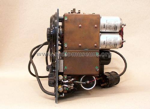
Universal Prüfsender SPU BN4114
Rohde & Schwarz, PTE; München
- País
- Alemania
- Fabricante / Marca
- Rohde & Schwarz, PTE; München
- Año
- 1949
- Categoría
- Aparato de medida y servicio (Equipo de laboratorio).
- Radiomuseum.org ID
- 120198
-
- alternative name: Messgerätebau Memmingen || Physikalisch-Technisches Entwicklungslabor Dr. Rohde & Dr. Schwarz


Haga clic en la miniatura esquemática para solicitarlo como documento gratuito.
- Numero de valvulas
- 3
- Gama de ondas
- Bandas de recepción puestas en notas.
- Tensión de funcionamiento
- Red: Corriente alterna (CA, Inglés = AC) / 110; 125; 150; 220 Volt
- Altavoz
- - Este modelo usa amplificador externo de B.F.
- Material
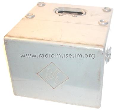
- Metálico
- de Radiomuseum.org
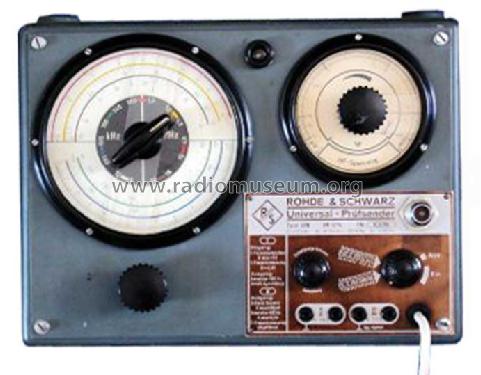
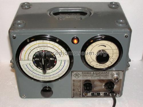
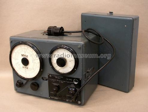
- Modelo: Universal Prüfsender SPU BN4114 - Rohde & Schwarz, PTE; München
- Forma
- Sobremesa de cualquier forma, detalles no conocidos.
- Ancho, altura, profundidad
- 300 x 220 x 200 mm / 11.8 x 8.7 x 7.9 inch
- Anotaciones
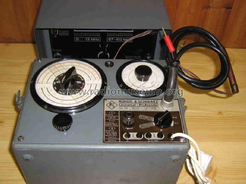
- Rohde & Schwarz SPU Universal Prüfsender;
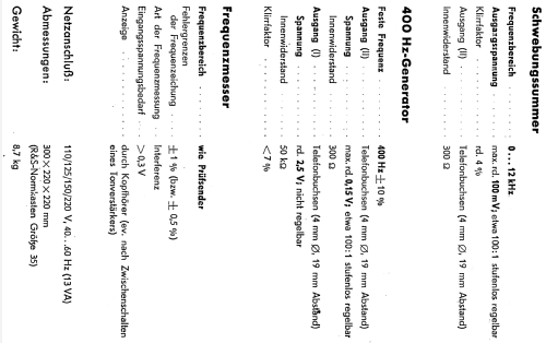
Signalgenerator, NF-Generator 10-12000 Hz; HF 0.1 - 30 MHz, AM-Modulation mit 400 Hz möglich.
- Peso neto
- 11.7 kg / 25 lb 12.3 oz (25.771 lb)
- Procedencia de los datos
- -- Collector info (Sammler)
- Mencionado en
- Funk-Technik (FT) (14/1949, S. 426)
- Documentación / Esquemas (1)
- Radio-Mentor (3/1950, S.126 f., Gerätebericht m. Schema)
- Otros modelos
-
Donde encontrará 552 modelos, 510 con imágenes y 253 con esquemas.
Ir al listado general de Rohde & Schwarz, PTE; München
Colecciones
El modelo Universal Prüfsender es parte de las colecciones de los siguientes miembros.
Contribuciones en el Foro acerca de este modelo: Rohde & Schwarz, PTE: Universal Prüfsender SPU BN4114
Hilos: 1 | Mensajes: 2
Hello Gentlemen,
After posting the 5 pages of techical data for the BN4114 unit from Archives of the USA offices of R&S, I wish to identify one anomaly with the factory data presented to me.
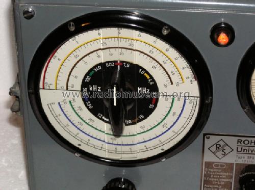
The front plate of the Signal Generator of the production model which I have in my possession; and the same front panel of the unit from the late member Wesselin Tzenow, depict the small Neon power ON indicator lamp (at the top center of the dial).
One additional item of concern relates to the technical data: since I have a copy of the Technical data folder 1148-87-b and the revised page "b" which pertains to the Output voltages values, there is no correlation to the "added" power ON neon lamp!!
Does any member have the technical data pages beyond page 4 of those sent to me from the USA office of Rohde & Schwarz?
I am preparing to begin the equipment checks to perform an alignment check on my early Argentin-produced Philips AL161 radio which has the IF requency of 175KHz. . . . .it appears as though the technical data states the IF wavelengths as being available from 330Khz up to 500Khz.
Am I seriously mistaken from the technical data??
Respectfully,
Robert
Robert Sarbell † 22.3.22, 17.Jun.11