Supersensitive Transistor Receiver
Sinclair Radionics Ltd.; St. Ives (Cambridge)
- Pays
- Royaume Uni
- Fabricant / Marque
- Sinclair Radionics Ltd.; St. Ives (Cambridge)
- Année
- 1958
- Catégorie
- Radio - ou tuner d'après la guerre 1939-45
- Radiomuseum.org ID
- 336877
Cliquez sur la vignette du schéma pour le demander en tant que document gratuit.
- No. de transistors
- Semi-conducteurs présents
- Semi-conducteurs
- Principe général
- Récepteur TRF - par réaction (régénératif)
- Circuits accordés
- 1 Circuits MA (AM)
- Gammes d'ondes
- PO uniquement
- Tension / type courant
- Batteries / Alim. BT séparée avec fiche / 1.2 Volt
- Haut-parleur
- - Pour casque ou amplificateur BF
- De Radiomuseum.org
- Modèle: Supersensitive Transistor Receiver - Sinclair Radionics Ltd.; St.
- Remarques
-
A theoretical, one transistor regenerative receiver by a young Clive Sinclair prior to starting Sinclair Radionics.
Transistor: PNP white-dot, germanium.
Battery: Mercury cell RM250.
See Forum Article.
- Littérature
- -- Original-techn. papers. (Practical Wireless March 1958, Page 18)
- Auteur
- Modèle crée par Gary Cowans. Voir les propositions de modification pour les contributeurs supplémentaires.
- D'autres Modèles
-
Vous pourrez trouver sous ce lien 42 modèles d'appareils, 40 avec des images et 19 avec des schémas.
Tous les appareils de Sinclair Radionics Ltd.; St. Ives (Cambridge)
Contributions du forum pour ce modèle: Sinclair Radionics: Supersensitive Transistor Receiver
Discussions: 1 | Publications: 1
A SINGLE-STAGE RECEIVER WITH NOVEL FEATURES
Supersensitive Transistor Receiver by Clive Sinclair
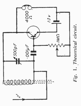
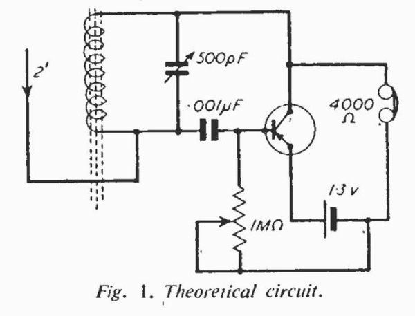
The majority of transistor receivers that have appeared in the press in the past have used crystal diodes for detection immediately after the first tuned circuit, the diode being followed by one or more stages of A.F. amplification. However, this type of receiver has little more sensitivity than a crystal set and is only really efficient with an external aerial of reasonable size. The reason for this is the crystal diode itself. The diode is non-linear in its rectifying ability and below a certain signal level, the efficiency is roughly proportional to the signal level. However. now that R.F. transistors are available at reasonable prices a really sensitive pocket receiver may be constructed without going to the complication and expense of a superhet. As may be seen from the diagram (Fig. 1) the circuit is of rather an unusual nature and has been designed to obtain the highest possible efficiency from a single transistor. Although the circuit appears very simple (the number of components has been kept to a minimum), the actual way in which it operates is surprisingly complex so no attempt will be made to go into details
Regeneration
The circuit is in fact a special form of regenerative detector in which oscillation automatically ceases when a station is accurately tuned in. All the components are readily available on the surplus market and the transistor used in the prototype was a white spot; this performed very reasonably.
Construction Several coil systems were tried out, but the best proved to be a Teletron FRM, ferrite rod aerial cut down to a length of 2". To do this remove the rubber grommet from one end of the ferrite. Now cut a groove on opposite sides of the rod and just about in the centre, using either a small file or a hacksaw. Then, holding one end of the rod in each hand, firmly snap it in two. The rubber grommet must now be replaced on the half of the ferrite which holds the coil. If you wish to wind your own ferrite rod aerial this can be done and the results are very little different if care is taken, e Sixty turns of D.S.C. or D.C.C. wire, 34 gauge, should be close wound in three layers right at the centre of a 2”, piece of ferrite rod ⅝” in diameter.
Tuning
If a really miniature receiver is required, then a trimmer must be used. This should have a maximum value of 500 µµF, although any value above 250 µµF will have sufficient capacity to tune in the Home, Light, and Luxembourg services. the Home being tuned when the value is approximately 200 µµF. If the existing screw is removed from the trimmer, one of the same gauge but greater length may be fitted, making it possible to sweat or bolt a suitable knob on.
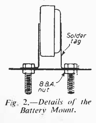
The battery used depends on the size to which you wish to keep the set. but if it is to be really small. a Mallory hearing aid cell, the RM250 should be used. This cell. which is obtainable from Boots the Chemists, is ideal as it has almost constant voltage with life enabling the station desired to be preset if necessary. The 1 megohm potentiometer is of the type used in hearing aids, and several firms sell these as surplus for about 1s. If they are equipped with an on /off switch this may, of course, be used but if there is none the set can be switched off merely by disconnecting the headphones.
The transistor itself can either be wired into the circuit or inserted in a suitable holder.
Operation
When the set has been completed and inserted into a suitable non-metallic case it should be tested in the following way:
Connect up an aerial of a few feet of insulated wire (a couple of yards will be sufficient in most areas), turn the volume control to maximum. and switch on by means of connecting up the headphones or hearing aid earpiece (4,000ít optimum).
Practical Wireless March 1958, Page 18.
Gary Cowans, 26.Mar.22