- Country
- United States of America (USA)
- Manufacturer / Brand
- Singer Company, The; La Vergne, TN
- Year
- 1960 ??
- Category
- Television Receiver (TV) or Monitor
- Radiomuseum.org ID
- 121928
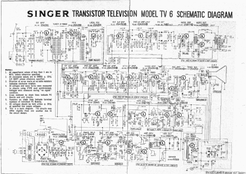
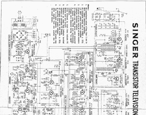
Click on the schematic thumbnail to request the schematic as a free document.
- Number of Tubes
- 2
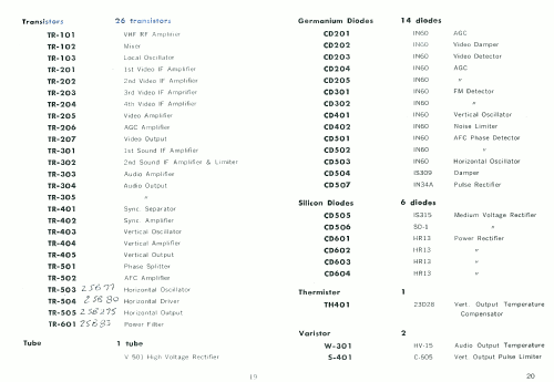
- Number of Transistors
- 26
- Semiconductors
- Main principle
- Superheterodyne (common)
- Wave bands
- VHF incl. FM and/or UHF (see notes for details)
- Power type and voltage
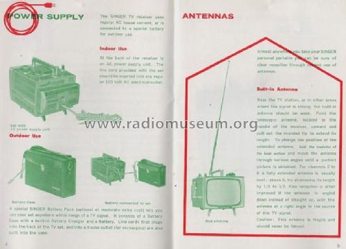
- Line / Storage batteries (perhaps also batteries) / 115; 12 Volt
- Loudspeaker
- Permanent Magnet Dynamic (PDyn) Loudspeaker (moving coil)
- Material
- Metal case
- from Radiomuseum.org
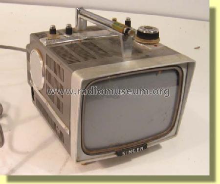
- Model: TV6 - Singer Company, The; La Vergne
- Shape
- Portable set > 8 inch (also usable without mains)
- Notes
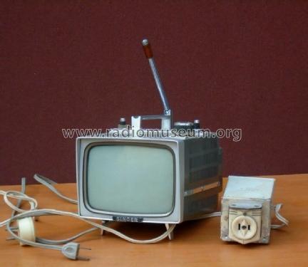
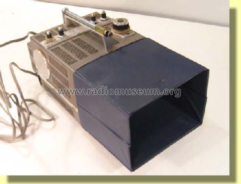
- 6" portable b/w TV, US band I/III drum tuner, built-in telescopic antenna, type TVA 3 was the special battery cord when used in a car.
- Source of data
- -- Collector info (Sammler)
- Author
- Model page created by a member from A. See "Data change" for further contributors.
- Other Models
-
Here you find 34 models, 27 with images and 2 with schematics for wireless sets etc. In French: TSF for Télégraphie sans fil.
All listed radios etc. from Singer Company, The; La Vergne, TN
Collections
The model TV6 is part of the collections of the following members.
Forum contributions about this model: Singer Company, The;: TV6
Threads: 1 | Posts: 1
Recent repair of two Singer TV6 units involved replacement of TR202 2SA234 in the second video IF stage. In one case the transistor was open, in the other case it developed excessive base resistance such that DC operation was OK, but there was no AC gain.
The IF frequency is not stated in the TV6 schematic, but I saw around 26MHz.
Before replacement of TR202, the set had no sound noise or image, but it had a white raster.
The electrical symptoms leading to the discovery of this common problem to both sets was a high gain of signal from 10mV p-p applied at the antena terminals for channel 10 around 200MHz, to the input of the second stage, while negligible signal appeared at the collector of TR202.
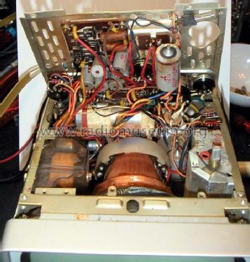
I got replacement transistors from a similar Singer TV6-U parts set. After these two transistors were replaced on each set there were still problems of a less severe nature. Note that the TV6-U is not just the TV6 with UHF added. The internal boards of the TV6-U look quite different from the internal boards of the TV6, which has no UHF.
One set had an open filter capacitor at the horizontal frequency control. It made horizontal lock impossible. This is C519 10uF at the Horizontal frequency control. probing the frequency control tap showed a large pulse train around 20Vp-p instead fo the expected pure DC control voltage.
This same set also had an open 100uF bypass capacitor C206 at the Video IF strip. This caused hum bars to roll vertically.
After these repairs, the remaining problem is poor vertical linearity on this set that with the two bad electrolytic caps. The linearity is bad enough that it can't be adjusted the with the vertical height, bias and linearity controls under the set. I have decided to put the set away for now, while documenting the work I did so far. The first thing I will check to solve the poor vertical linearity problem are the many electrolytic capacitors in the Vertical amplifier.
Comments invited.
-Joe Sousa
p.s.: A full scan of the manual showing all TV6 accessories and schematic is available at TV6_Manual
Joe Sousa, 09.Dec.08
