515P
Sobell Ind., Slough
- Land
- Grossbritannien (UK)
- Hersteller / Marke
- Sobell Ind., Slough
- Jahr
- 1954
- Kategorie
- Rundfunkempfänger (Radio - oder Tuner nach WW2)
- Radiomuseum.org ID
- 79393
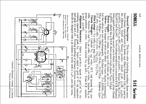
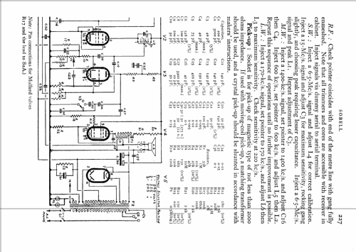
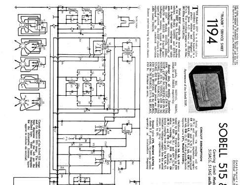
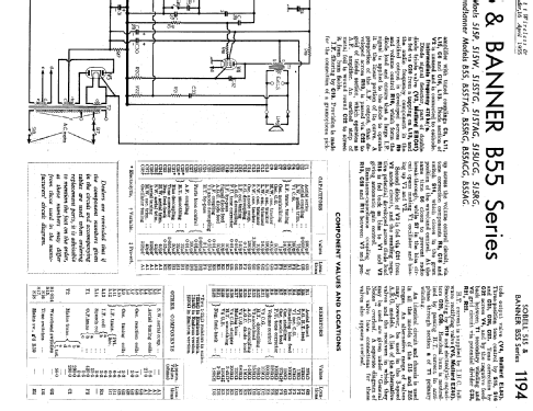
Klicken Sie auf den Schaltplanausschnitt, um diesen kostenlos als Dokument anzufordern.
- Anzahl Röhren
- 5
- Hauptprinzip
- Superhet allgemein; ZF/IF 470 kHz
- Wellenbereiche
- Langwelle, Mittelwelle und Kurzwelle.
- Betriebsart / Volt
- Wechselstromspeisung / 200-250 Volt
- Lautsprecher
- Dynamischer LS, Prinzip (Edyn oder Pdyn) nicht gegeben.
- Material
- Bakelit (Pressstoff)
- von Radiomuseum.org
- Modell: 515P - Sobell Ind., Slough
- Form
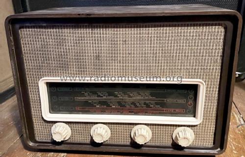
- Tischgerät-gross, - Querformat (breiter als hoch oder quadratisch).
- Abmessungen (BHT)
- 16 x 11.5 x 7 inch / 406 x 292 x 178 mm
- Bemerkung
- identical to H.M.V.1360.
- Datenherkunft
- Radio! Radio!
- Autor
- Modellseite von Konrad Birkner † 12.08.2014 angelegt. Siehe bei "Änderungsvorschlag" für weitere Mitarbeit.
- Weitere Modelle
-
Hier finden Sie 116 Modelle, davon 69 mit Bildern und 90 mit Schaltbildern.
Alle gelisteten Radios usw. von Sobell Ind., Slough
Forumsbeiträge zum Modell: Sobell Ind., Slough: 515P
Threads: 2 | Posts: 6
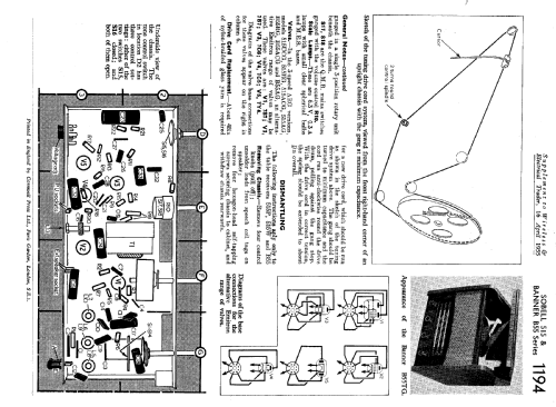
Still not terribly sure if I am doing this the right way according to forum rules, but I got the chance to spend some time with my Sobell 515P, and all of the data sheets I can find indicate that V2 is an EAF42. On my set V2 is an EF89.
This is an 8 pin base, and pulling up the comparison, I find the whole pin out to be different, and the original diagram shows L13 to be mounted on the back of the chassis.
I am wondering if there has been a lot of surgery on this model long ago (for none of it looks disturbed), or if indeed, it is a different circuit which has been employed, perhaps in order to allow the EF89 rather than the original EAF42.
The characteristics are similar, but not identical, and pin 6 is certainly not the grid on the EF89.
Any hints please?
David MacFarlane, 26.Jan.19
Hi, I'm new to Rmorg, and not terribly sure if I am entering in the corresct fashion, nor indeed if anyone might get to see this, - fantastic and complex as the org is, but here goes -
I acquired a Sobell 515p some time ago, and have had difficulty in receiving stations on sw, mw or lw.
I tried adjusting the If's an tuning coils ever so slightly, bringing them back to where they were when I got no result.
I was about to inject signals as per textbook instruction, when I noticed that the valves seemed to be very different from the book diagrams.
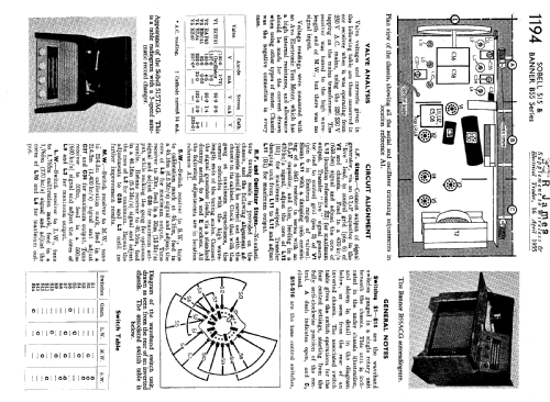
The book says V1 to V5 respectively, are ECH81, EF41, EBC41, EL84 AND EZ40.
The line up in this old set is as follows - ECH81, EF89, EL84, EBF80 AND EZ80, Again, respectively V1 to V5.
I am not even sure that EL84 is in the right order, although in one of the sketches, V3 and V4 seemed to change places, which would allow EL94 to be correct.
The rest of the valves do not seem to figure, since EF41 and EBC41 are different bases.
I cannot see the similarity between EF89 and EF41, unless the bases have been swapped, but there is no evidence of this, and it seems an unlikely candidate. Can anyone help?
Dave.
David MacFarlane, 15.Dec.18
