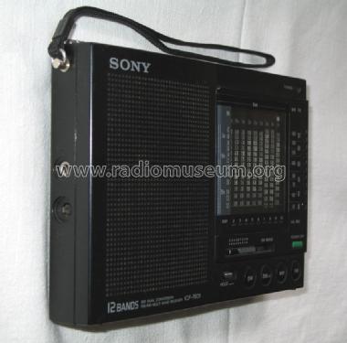
FM/AM Multi Band Receiver ICF-7601
Sony Corporation; Tokyo
- Country
- Japan
- Manufacturer / Brand
- Sony Corporation; Tokyo
- Year
- 1987 ?
- Category
- Broadcast Receiver - or past WW2 Tuner
- Radiomuseum.org ID
- 186332
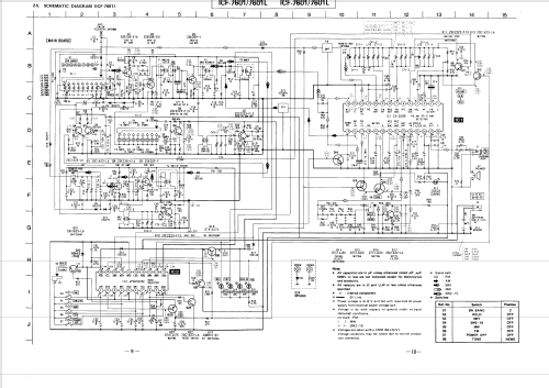
Click on the schematic thumbnail to request the schematic as a free document.
- Number of Transistors
- 21
- Semiconductors
- CX20091
- Main principle
- Superhet, double/triple conversion
- Wave bands
- Broadcast, Short Wave plus FM or UHF.
- Power type and voltage
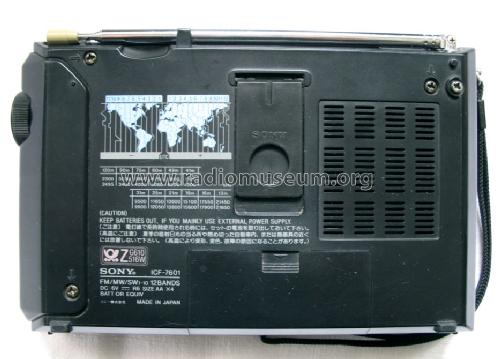
- Batteries / addl. power jack / AA: 4 x 1.5 / 6 Volt
- Loudspeaker
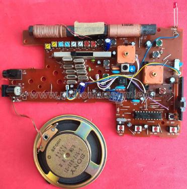
- Permanent Magnet Dynamic (PDyn) Loudspeaker (moving coil) / Ø 7.7 cm = 3 inch
- Power out
- 0.45 W (unknown quality)
- Material
- Plastics (no bakelite or catalin)
- from Radiomuseum.org
- Model: FM/AM Multi Band Receiver ICF-7601 - Sony Corporation; Tokyo
- Shape
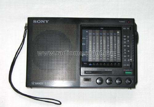
- Very small Portable or Pocket-Set (Handheld) < 8 inch.
- Dimensions (WHD)
- 185 x 118 x 33 mm / 7.3 x 4.6 x 1.3 inch
- Notes
-
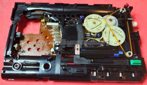
Sony model ICF-7601 is equipped with two ICs (IC1 CX20091 for FM, AM, RF/IF, Detector, Audio Amp and IC2 µPD65005C198 for SW1/SW2-10/MW/FM band switching and Power Off).
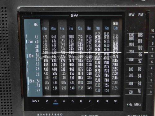
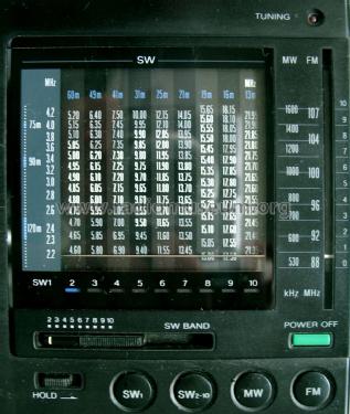
Shortwave coverage: 120-75 / 60 / 49 / 41 / 31 / 25 / 22 / 19 / 16 / 13 m band, analog readout, no single sideband.
There are two variants according to the service manual:
- for West Germany, Saudi Arabia: FM: 87.6 - 107 MHz, MW: 525 - 1610 KHz
- for US, Canada, AEP, and E extended coveragew: FM: 76 - 108 MHz, MW: 530 - 1705 KHz
A similar model intended for the European market Sony model ICF-7601L is equipped with LW instead of the SW band 120-75 m.
- Net weight (2.2 lb = 1 kg)
- 0.6 kg / 1 lb 5.1 oz (1.322 lb)
- Literature/Schematics (1)
- -- Original-techn. papers.
- Author
- Model page created by Arpad Roth † 27.3.17. See "Data change" for further contributors.
- Other Models
-
Here you find 4048 models, 3906 with images and 970 with schematics for wireless sets etc. In French: TSF for Télégraphie sans fil.
All listed radios etc. from Sony Corporation; Tokyo
Collections
The model FM/AM Multi Band Receiver is part of the collections of the following members.
Forum contributions about this model: Sony Corporation;: FM/AM Multi Band Receiver ICF-7601
Threads: 1 | Posts: 1
Got this radio yesterday. It do nor power off, erratic band switching, SW2-10 LED allways ON.
I was afraid that the IC2 UPD-65005C-198 (D65005C198 ) Sony Part # 8-759-141-09 was defective, as reported elsewhere in the internet. This is customized NEC gate array with a somewhat complex true table using output latches with power buffers to handle the required current for the different radio sections.
Checking the IC2 pin 20 Vdd shoed 5.3V, about right if we add 0.7V dropping from the D16 diode that is connected to the +6V battery. Also all other IC2 outputs looked to respond as expected, only the voltage levels were incorrect. Strangely the IC pin 19 was going to high voltage when pressing the power off button, wich looks correct, despite the Q19 transistor not cutting off the power to the IC1 chip.
Q19 was good, also it do not explain the band switching wrong voltage levels.
Then I decided to use the good old technique to sistematically test all components around IC2, and yes, I found diode D16 to be open! So, despite being open, IC2 still manage to get the "correct" power supply voltage. Stange. Then I realize this IC2 is a CMOS chip, so D16 being opened still manage to pass some current acting as a high resitor to the CMOS chip.
After replacing D16 (1SS148) with a more modern 1N4148, all operation was restored.
My guess to the cause of this failure was the use of an external power adapter that applied over-voltage causing the protection Zenner diode D22 to conduct forcing excessive current on the series diode D16 that blew up as a fuse.

Jose Mesquita, 26.Sep.20
